NeuropixelsV1e GUI
The NeuropixelsV1e headstage has a graphical user interface when the OpenEphys.Onix1.Design
package is downloaded. For more information on how to install that library, check out the
Installation page.
Overview
For HeadstageNeuropixelsV1e, the GUI allows for an easy way to change settings and visualize the
effect. From the GUI, you can:
- Configure the NeuropixelsV1ProbeConfiguration
- Choose the ADC calibration file
- Choose the gain calibration file
- Choose the AP and LFP gain values
- Enable or disable the AP-band spike filter
- Choose to invert the polarity of the data
- Change the reference for all electrodes
- Choose and edit the ProbeInterface configuration file
- Choose pre-defined channel presets or manually define within a constrained set of possible combinations
- Easily visualize which electrodes are enabled
- Configure the Bno055
- Enable and disable the PolledBno055Data stream
Opening the GUI
To open the headstage configuration GUI, double-click the ConfigureHeadstageNeuropixelsV1e operator.
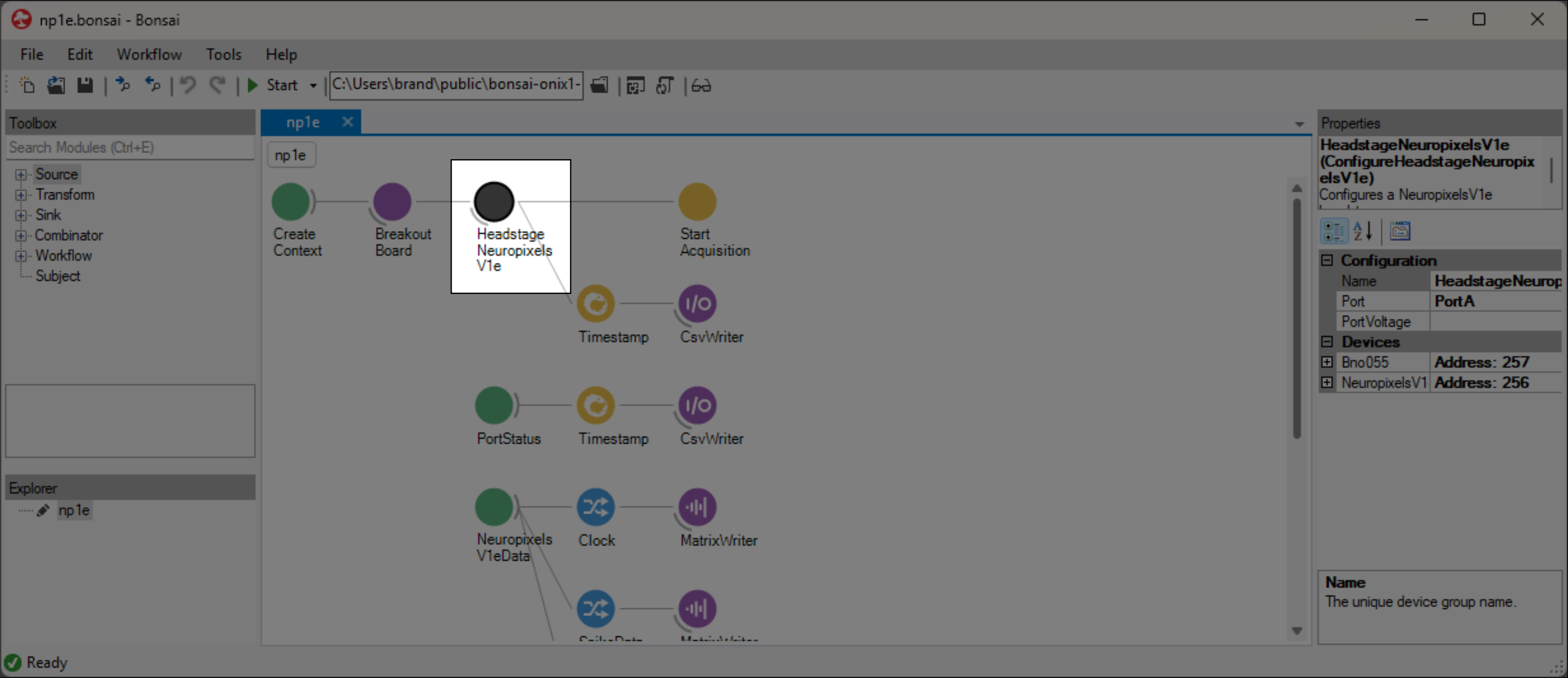
Once opened, if the calibration files have not been selected the window should look like the image below. To view the probe, follow the steps below to choose calibration files.
Channel constraints
For NeuropixelsV1e, there will always be 384 channels enabled across the entire probe. Therefore,
when enabling electrodes (either manually or using channel
presets), some previously enabled electrodes will be disabled. Additionally, if
more than 384 electrodes are manually selected to be enabled, only the last 384 channels will end up
being enabled. It is therefore recommended to always double-check that the correct electrodes are
enabled.
As an example, let us assume that electrodes 0 through 383 are initially enabled (this
corresponds to 384 channels). Then, electrodes 384 and 385 are enabled. When these electrodes
are enabled, electrodes 0 and 1 will be disabled. In this way, there will always be 384 channels
enabled.
In addition to the absolute number of channels, there are other restrictions in place regarding
which combinations of electrodes can be enabled at any given time. Specifically, in the
NeuropixelsV1Electrode there is a Channel property which defines the
channel index of an electrode. Across the entire probe, no two electrodes that share the same
Channel can be simultaneously enabled.
Channel presets take this into account automatically and ensure that the rules
are followed. When manually enabling electrodes, the indexing logic is applied in the order that
electrodes are selected. If two (or more) electrodes are selected that share a Channel value, the
highest indexed electrode is the only one that will be enabled.
Note
Due to these constraints, it is possible that a desired combination of electrodes is not feasible.
Keeping or discarding configuration settings
While the GUI is open, any changes to the configuration settings can be freely modified. Most changes will not be saved unless OK is pressed. This includes the chosen reference channel and probe calibration file. However, the electrode configuration as described below can be saved independently of the other configuration settings.
Note
The hardware is not actually configured until the workflow starts.
If the window is closed any other way (such as by pressing Cancel, or pressing the X to
close the window), then any configuration changes made will not be saved.
ProbeInterface
The HeadstageNeuropixelsV1e GUI uses
ProbeInterface as the format to save and
draw the probes and electrodes visually. For more information on ProbeInterface and the resulting
JSON file, check out their format
specifications page.
When opening the GUI, there is a default probe configuration that is loaded and drawn, which can be saved to a JSON file. Conversely, an existing JSON file can be loaded to update the current channel configuration. If for any reason the default configuration is needed, it can be loaded again at any time.
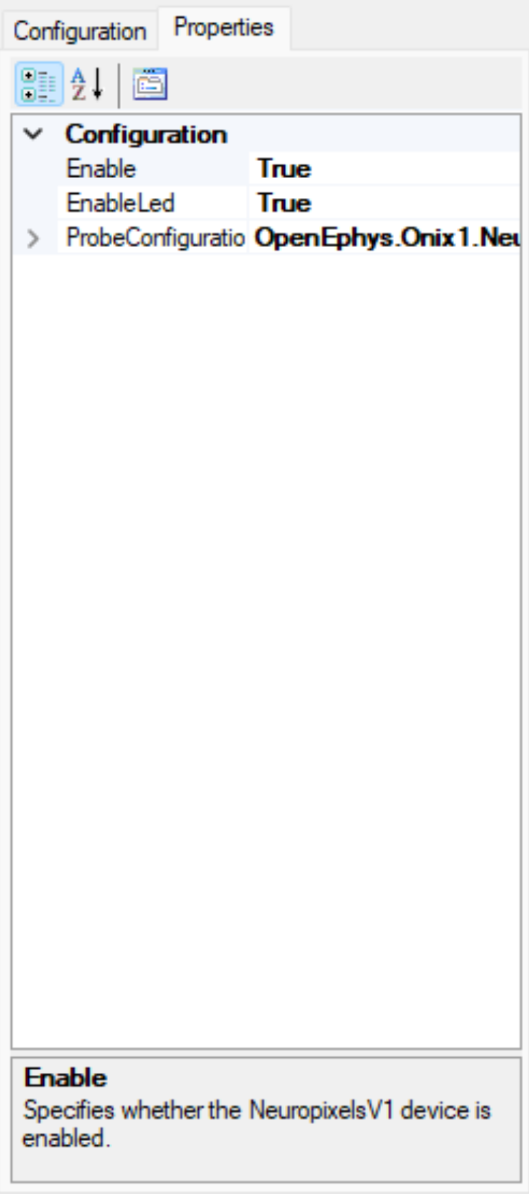
Neuropixels V1 Probe Configuration
An alternative view of the properties can be found by clicking on the Properties tab, which will
show a property grid similar to what is shown by the Bonsai editor.
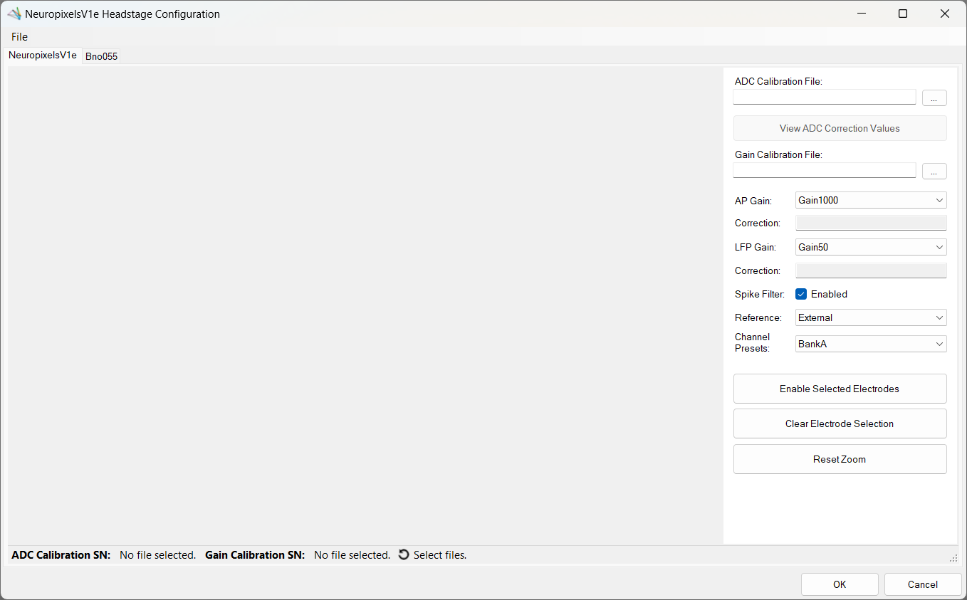
Choosing probe calibration files
Upon opening the GUI for the first time, if no probe calibration files were set in the Bonsai
editor, the window will be mostly blank. To populate the window with a drawing of the probe, both
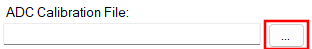
calibration files must be selected. First, click on the ... button to the right of the
empty text box under "ADC Calibration File" (see below). This will open a file dialog, where the ADC
calibration file can be searched for and selected. Once the file is selected, press Open or
Enter. This will populate the text box with the filepath to the calibration file.
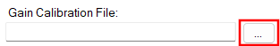
This process is then repeated for the gain calibration file; click on the ... button to
the right of the empty text box under Gain Calibration File (see below). This will open a file
dialog, where the gain calibration file can be searched for and selected.
Note
Files are expected to be named XXXXXXXXXXX_ADCCalibration.csv and
XXXXXXXXXXX_gainCalValues.csv, where "XXXXXXXXXXX" is the probe serial number.
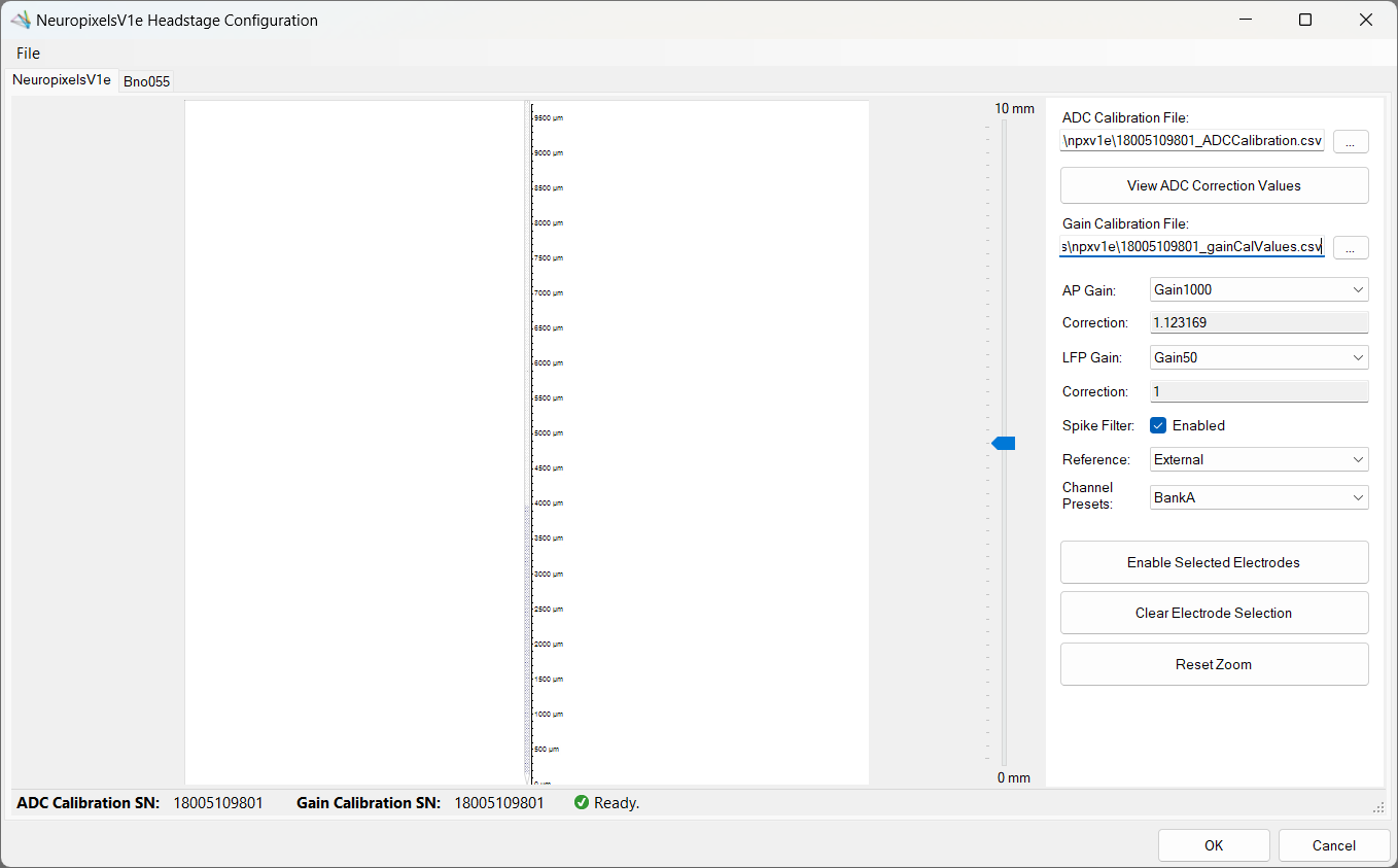
Once both files are selected, this will enable visualization of the electrodes. Below is a view of the configuration GUI that has been opened after both calibration files have been selected.
Status strip
Towards the bottom of the GUI, there is a status strip that reports the current ProbeInterface file and the serial number found in the selected calibration files. Next to the reported serial numbers is a status symbol indicating if there any potential issues. Below is a list of possible states the status strip will display for serial numbers:
| Symbol | Reason |
|---|---|
 |
One or no files are selected |
 |
One or more files are invalid |
 |
Different serial numbers reported |
 |
Files are valid, and serial numbers match |
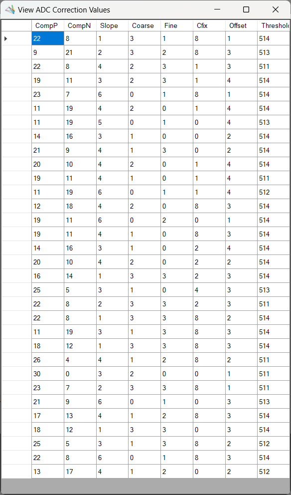
View ADC correction values
Once a valid ADC calibration file has been selected, the View ADC Correction Values button will be enabled. This button can be pressed to open a new dialog that displays the correction values for all ADCs. Refer to NeuropixelsV1Adc for more details on the specific calibration values.
Selecting AP gain
The gain for the AP-band can be selected from the dropdown menu next to AP Gain. For a list of
possible gain values, check out NeuropixelsV1Gain. If a gain calibration file
has been selected and is valid, the gain correction that will be applied is displayed in the textbox
underneath the dropdown menu and is updated based on the current gain selected.

Selecting LFP gain
The gain for the LFP-band can be selected from the dropdown menu next to LFP Gain. For a list of
possible gain values, check out NeuropixelsV1Gain. If a gain calibration file
has been selected and is valid, the gain correction that will be applied is displayed in the textbox
underneath the dropdown menu and is updated based on the current gain selected.

Enabling spike filter
A checkbox allows enabling or disabling of the spike-band filter. If enabled, the spike-band has a 300 Hz high-pass filter which will be activated. If set to false, the high-pass filter will not to be activated.
Inverting the polarity of ephys data
A checkbox indicates whether the ephys data will be inverted or not. This option is enabled by default, as Neuropixels hardware inverts neural data; therefore, leaving this option enabled will invert the data again, matching the data recorded by the Open Ephys GUI or other hardware sources.
Selecting channel reference
Underneath the probe calibration filepath, there is a dropdown menu for choosing the reference for all channels. For possible values and a brief description of what they correspond to, check out the references page.

Channel presets
To save time, it is possible to select a preset channel combination from the Channel Presets
dropdown. These presets are defined to work within the constraints of NeuropixelsV1e channel
combinations defined above.
Below is a list of available channel presets:
- Bank [A | B | C]
- Enables all electrodes in the chosen bank
- To learn more about banks, check out NeuropixelsV1Bank.
- Single Column
- Enables all even electrodes on Bank A, then all odd electrodes on Bank B
- Tetrodes
- Enables the first group of four electrodes for every eight electrodes (electrodes 0-3 but not 4-7) in Bank A, then enables the second group of four for every eight electrodes in Bank B (388-391, but not 384-387).
If electrodes are manually enabled, the Channel Presets dropdown will change to None,
indicating that a channel preset is no longer selected.
Maneuvering along the probe
Once a GUI has been opened and a probe calibration file has
been selected, the main panel on the left will be populated
with a NeuropixelsV1e probe. Below are the buttons used to navigate within this panel to view and
choose electrodes.
- Mouse Controls
- Mouse wheel zooms in/out towards the cursor
- Left-click and drag will select electrodes within the drawn rectangle
- Left-click on an electrode will toggle that electrode
- Left-click in empty space will clear the selected electrodes
- Middle-click and drag will pan the electrodes
- Scroll bar
- On the right side of the main panel there is a scroll bar that can be used to move the probe up and down
- Panning the probe up or down will update the scroll bar once the movement has completed
- The scroll bar can be moved by:
- Grabbing the marker using the mouse and dragging it up or down
- Placing the cursor either above or below the marker and clicking
- Using the mouse wheel to scroll up or down while the cursor is over the scroll bar
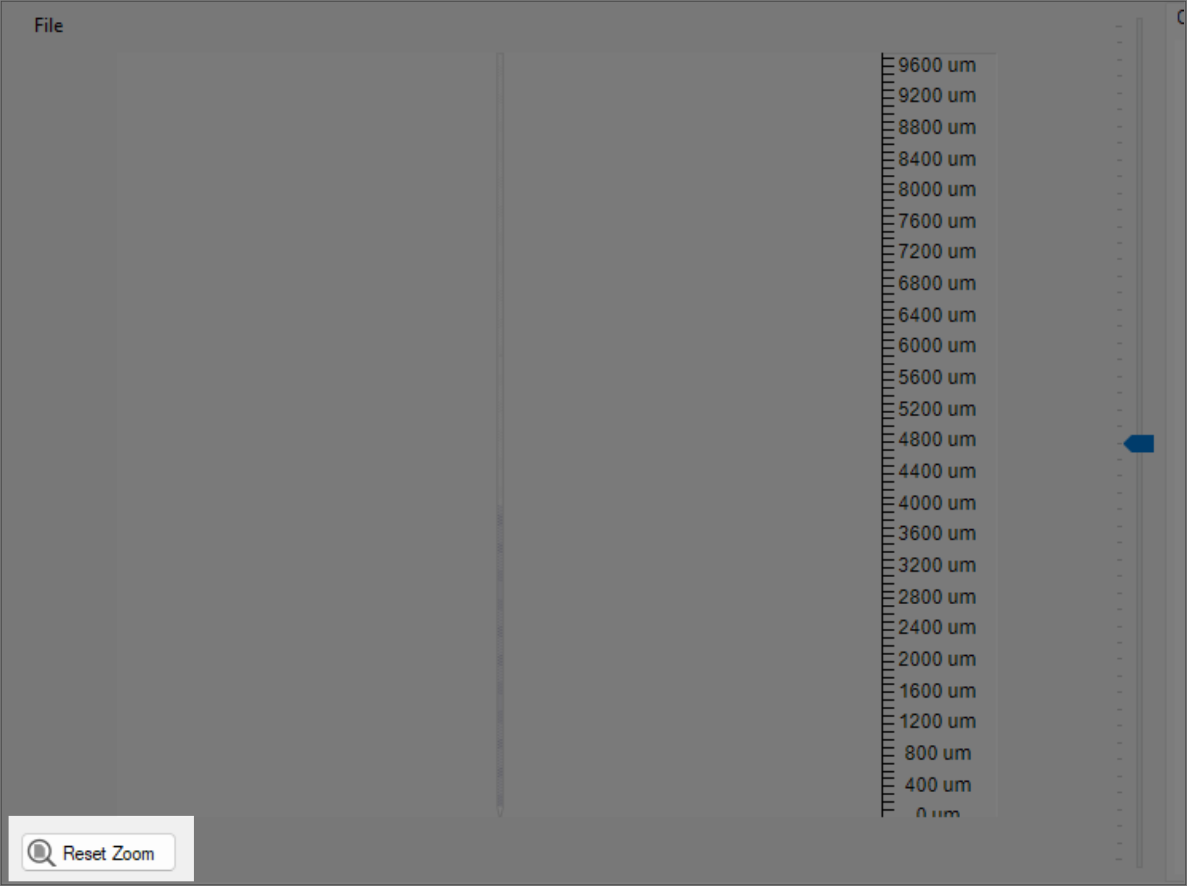
Reset zoom
When zooming in and out, there are limits in both directions. The probe can only be zoomed out to the point that the entire probe is visible within the panel, and similarly the probe will not zoom in past a certain point.
There are no restrictions when panning the probe, meaning that it is possible to move the probe to
where it is out of view, and difficult to find. To reset the view at any time, click on the Reset Zoom button to fully zoom out the panel.
Manually enabling electrodes
Electrodes can be selected at any zoom level, but it is often preferable to zoom in to read the electrode indices. Consider maximizing the window to see those numbers more easily.
To select, as described above, either click-and-drag the cursor over
the desired electrodes, or select individual electrodes by clicking on them one-by-one. Once the
electrodes to enable are selected, click on the Enable Selected Electrodes button in the right
panel. At this point the selected electrodes should turn blue, indicating that they are now enabled.
It is important to note that when electrodes are enabled, some previously enabled electrodes
will be disabled due to channel constraints. For more information, read the Channel
constraints section above.
The short video below shows how to select, clear selection, enable selected electrodes, and
translate using the scroll bar. Note that once electrodes are manually enabled, the Channel Presets drop-down changes from BankA to None. Then, once the selected electrodes match the
preset, it is automatically changed back to BankA.
Loading and saving channel configurations
When the GUI is first opened and after a probe calibration file has been specified, the default
ProbeInterface configuration is loaded and drawn in the main panel. In this case,
the default configuration is for a single-shank NeuropixelsV1e probe, with the BankA channel
preset selected. To load a new configuration, load the default configuration, or save the current
configuration, go to the File drop-down menu (see below) and choose the relevant option.

Open ProbeInterface file
To open a file, navigate to the file menu option File → Open or press Ctrl + O. This
will open a file dialog window; browse to the existing JSON file, select it and press Open to view
the channel configuration. The new probe will be loaded and drawn, with the enabled electrodes
highlighted.
The ProbeInterface File section of the status bar will update to display the filename that was
selected. To view the entire filepath for the file, hover over the filename to display a tooltip
with the entire filepath.
Save ProbeInterface file
Whenever changes are made to the ProbeInterface configuration, an asterisk will appear on the tab or
title of the window to indicate that some changes to the electrode configuration are unsaved. To
save the file, go to the file menu option File → Save or press Ctrl + S.
- If there is not a filename already selected, this will open a file dialog window to save a new
file. Choose a folder location and a name for the file, then hit
Save. - If a filename is already selected, then the file will be immediately saved to the current
filepath, overwriting the channel configuration.
- If you do not want to overwrite the channel configuration, you can instead use
File → Save Asor Ctrl + Shift + S to save the current electrode configuration to a new filepath.
- If you do not want to overwrite the channel configuration, you can instead use
If there are unsaved changes to the electrode configuration, pressing Cancel will discard all unsaved changes. If the electrode configuration is first saved to a file, and then Cancel is pressed, the changes are still saved in the file; however, other probe configuration properties such as the ProbeInterface file name or the reference used, will be discarded. When OK is pressed and there are unsaved changes, a prompt will appear confirming if you would like to save, save as, or cancel closing the dialog.
Import configuration
Instead of opening a file and updating the ProbeInterface filename, you can instead choose to import
another configuration by going to File → Import Configuration. This will open up a Load File
dialog, where you can select an existing ProbeInterface file that will be imported without modifying
the current filename.
Load default configuration
To load the default channel configuration at any time, navigate to the drop-down menu and choose
File → Load Default Configuration. This will load the default configuration, with the BankA
channel preset selected.
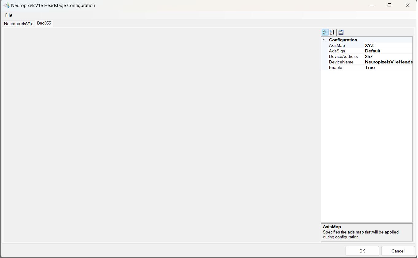
Configure Bno055
At the headstage level, there is another device tab listed for a
Bno055. From this tab, the device can be enabled or
disabled by selecting the appropriate value from the drop-down menu next to Enable. While other
properties are displayed here, they have no effect on the underlying device configuration; only
changes to the Enable property will be respected.