Calibrate Positional Tracking Data
This tutorial shows how to transform XYZ position coordinates measured by a TS4231 device which are originally in the device's reference frame to coordinates that are in a reference frame that is more intuitive or relevant to the experiment. This is performed by determining the position coordinates of four points in both the TS4231 device's reference frame and the user-defined reference frame to calculate a spatial transform matrix which transforms all coordinates measured by the TS4231 device to the user-defined coordinate system.
Setup
First, confirm the Lighthouse transmitters are properly mounted according to the Lighthouse Setup Guide in the ONIX Hardware docs.
Follow the Getting Started guide to set up and familiarize yourself with Bonsai. In particular, download the necessary Bonsai packages or check for updates if they're already installed.
Copy the following workflow into the Bonsai workflow editor by hovering over the workflow image and clicking on the clipboard icon that appears.
Open Bonsai and paste this workflow by clicking the Bonsai workflow editor pane and pressing Ctrl+V.
Visit the Headstage 64 Example Workflow and Headstage 64 Ts4231 pages to develop a foundation on how to use Bonsai to acquire data from an ONIX headstage that has a TS4231 device.
Before beginning the calibration process, confirm that the lighthouse configuration can measure the position of your TS4231 device across the entire desired range. To do this, start the workflow and confirm that the TS4231V1PositionData operator continually produces data as you slowly move the headstage across the entire range of your arena while inspecting the TS4231V1PositionData Position visualizer. If at some point the TS4231V1PositionData operator stops producing data during this process (e.g. the Position visualizer stops updating), the TS4231 receivers are either obstructed from or no longer within range of the Lighthouse base station transmitters. Remedying this might require modifying the lighthouse configuration or reducing the size of your arena.
Tip
The simple linear transform that this tutorial implements fails to consider non-linearities that the lighthouses exhibit at large distances. For accurate calibration using the linear transform node in this tutorial, the size of the arena might need to be constrained. More advanced calibration methods can be more accurate over larger spaces.
TS4231 Spatial Data Calibration
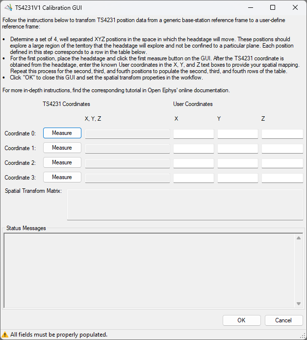
Open the TS4231V1 Position Calibration GUI.
- Start the workflow.
- Open the TS4231V1LinearTransform Position visualizer.
- Click TS4231V1LinearTransform node to show its properties in the properties panel.
- Click the ... next to the "SpatialTransform" property.
Mark four points in your behavioral arena. The position coordinates of these four points will be measured both in the TS4231 reference frame by the TS4231 device itself and in the user-defined reference frame. Here is a simple way to choose the four points:
- The user-defined origin
- A point in the behavioral arena along the user-defined X-axis
- A point in the behavioral arena along the user-defined Y-axis
- A point in the behavioral arena along the user-defined Z-axis
Tip
Choosing the furthest extent along the X, Y, & Z axes minimizes the propagation of measurement error into the spatial transformation matrix.
Here is a real-world example of four sets of coordinates on our workbench that we use to demonstrate the calibration process:
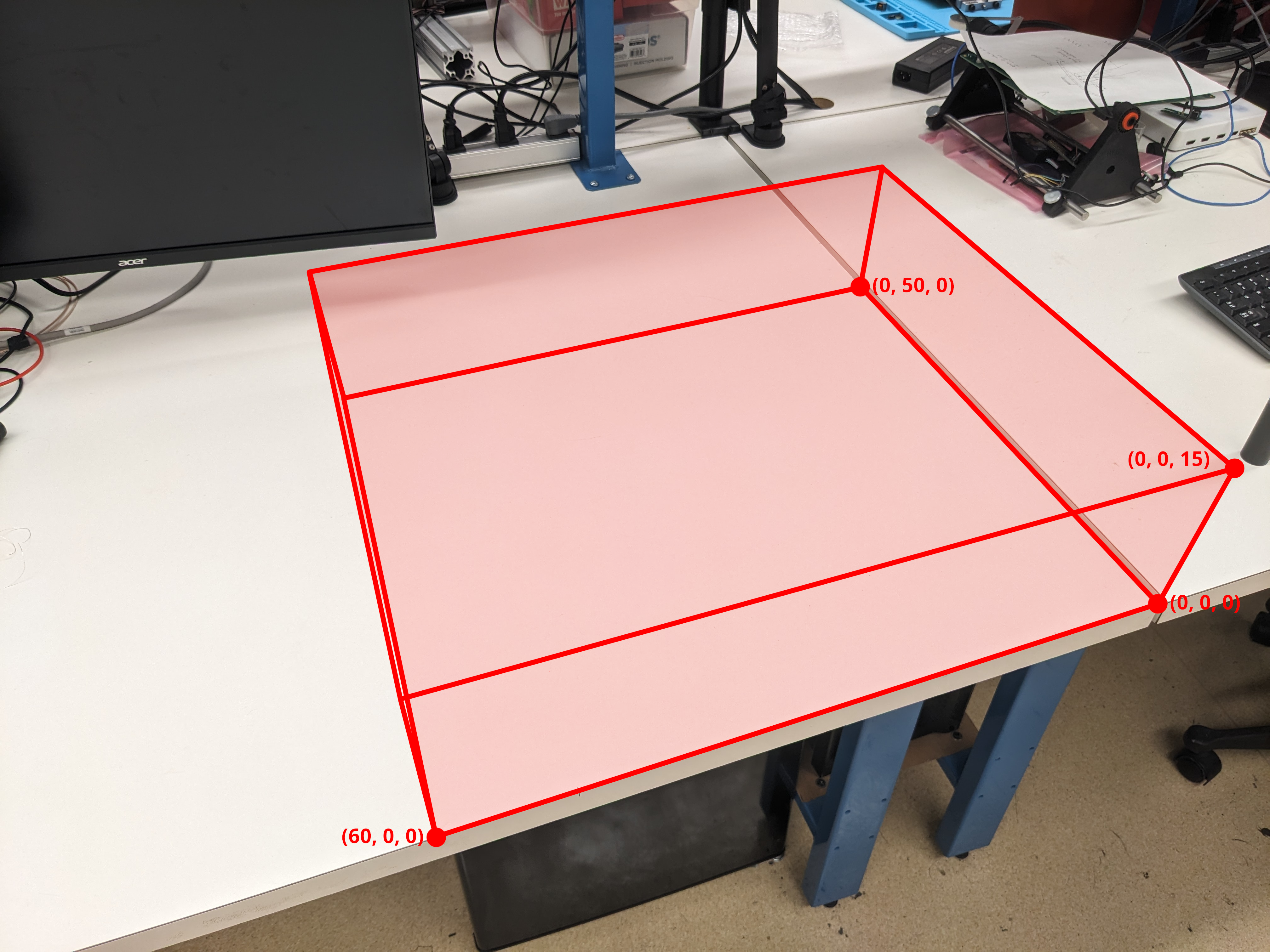
The light red space is an arbitrarily-defined working area for this demo. Units are in cm.
For each of the four points defined in the previous step:
- Choose a row in the TS4231V1 Calibration GUI to correspond to that point.
- Place your TS4231 device at that point and click the Measure button in the corresponding row. The GUI will start taking measurements from the TS4231 device as long as the TS4231 device is within range of and unobstructed from the lighthouse transmitter. If the TS4231 measurement completes successfully, the corresponding entry in the form is automatically populated. Otherwise, that entry stays empty. In either case, you will be informed of the result in the "Status Messages" text box. If the TS4231 measurement fails, return to the step in the previous section that describes how to make sure the lighthouse configuration covers the entire area that your TS4231 device will occupy.
- Populate the X, Y, and Z entries of the user-defined coordinates column in the corresponding row.
Tip
Be as precise and accurate as possible with both the placement of the TS4231 device and the manual measurements. Consider making a fixture to fix the orientation of the TS4231 device and help set it in positions that are more easily measured.
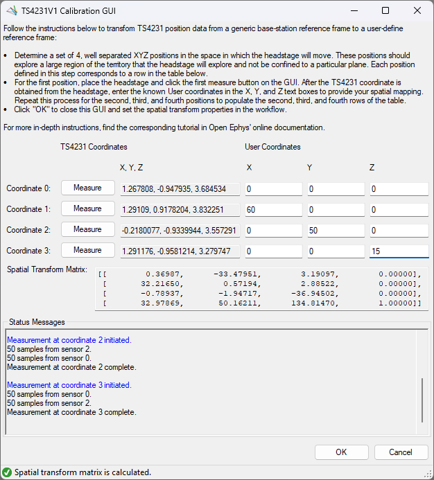
Once all fields in the Calibration GUI are populated with valid entries, the spatial transform matrix is automatically calculated. When the spatial transform matrix is calculated, this will be indicated in the GUI's bottom status strip and the spatial transform matrix text box such as in the following screenshot:
After the spatial transform is calculated, click OK to proceed. This updates the spatial transform matrix used by the TS4231V1LinearTransform operator. This recalibrated spatial transform matrix should be immediately apparent in the TS4231V1LinearTransform position data visualizer.
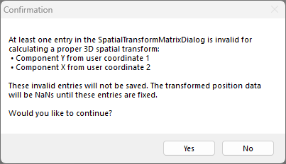
If you are presented with the following confirmation, return to the TS4231 Calibration GUI main form to fix the entries that were indicated invalid in the confirmation dialog.
Important
After calibrating the TS4231V1 spatial transform matrix, it is important to not change the TS4231PositionData operator's P or Q property values or move the lighthouse base stations. If anything is changed, the calibrated spatial transform matrix will no longer be accurate.
Verify TS4231 Calibration
After following the previous section, visualize the calibrated data and confirm that the transformed data matches your expectations. Inspecting the Position visualizer in Bonsai while moving the TS4231 device is a first-order test. Choose several points (none of which should be the four calibration points) and check that their calibrated coordinates are what you expect.
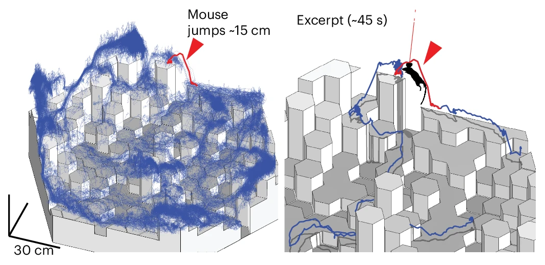
Below is an animation of the 3D trajectory reconstructed in Python synced with video data for demonstration purposes.