Visualizing Data in the Open Ephys GUI
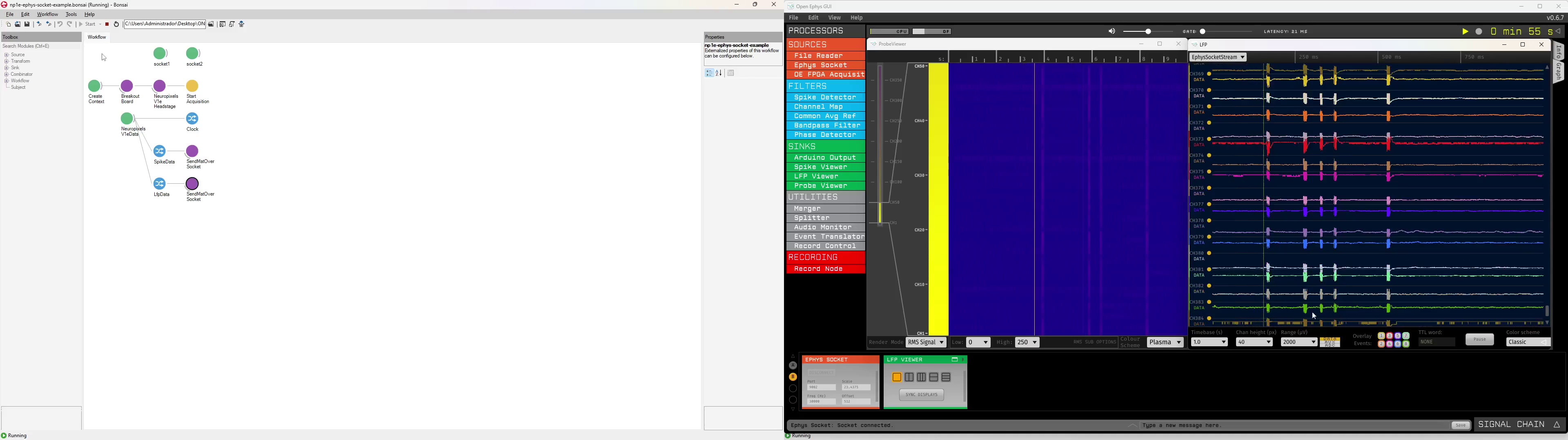
This tutorial shows how to stream ephys data from Bonsai the Open Ephys GUI through an intermediary TCP connection. This approach lets users take advantage of both the extensibility of Bonsai and specialized visualizers available in the Open Ephys GUI such as the Probe Viewer which is specifically designed for very dense arrays like Neuropixels probes. By the end of this tutorial, you will have a workflow that transmits two data streams from a NeuropixelsV1e headstage (384 channels of LFP band and AP band data) and an Open Ephys GUI signal chain that receives and visualizes the two data streams in the Open Ephys GUI:
Note
- This tutorial uses NeuropixelsV1e Headstage as an example, but the process is similar for other ephys headstages. In fact, this tutorial can be used to send data from any Bonsai operator that produces matrices.
- This tutorial assumes you are familiar with the Data Acquisition Quick Start guide for the ONIX headstage you intend to use.
- A video summary of this tutorial is available at the bottom of this page.
Transmit Ephys Data to a TCP Server in Bonsai
Follow the Getting Started guide to set up and familiarize yourself with Bonsai. In particular, download the necessary Bonsai packages or check for updates if they're already installed. Once you've done that, copy/paste the following workflow into your Bonsai editor. The following sections explain how to create this workflow and configure its elements.
Configure TCP Connection
Place one TcpServer node per datastream at the top of the workflow and
set their properties:
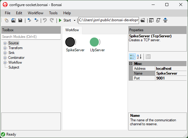
- Address: Use "localhost" if you are running Bonsai and the Open Ephys GUI on the same machine. Use the IP address of the machine running the GUI if not.
- Name: give the TCP server a unique name. This name is used later in the the workflow to specify to which server to send data. In this example, we have named them "SpikeServer" and "LfpServer". These names are arbitrary, but in our example they correspond to the kind of data they will transmit.
- Port: choose a unique port number. We will use this port number to establish the connection with the Open Ephys GUI. This must be unique for each datastream that you wish to send. We used 9001 for our spike data and 9002 for LFP data.
Important
The TcpServer nodes need to be at the top of the workflow. If they end up somewhere else and you need to move them, do the following: click and hold on the node, hold down the Alt key on the keyboard, hover over a node in the workflow row over which you want to place it until an arrow appears, and let go. To learn more about moving nodes and connections in the workflow, refer to our Workflow Editor page.
Configure ONIX Hardware
Construct an ONIX hardware configuration chain:
- Place the configuration operators that correspond to the hardware you intend to use between CreateContext and StartAcquisition. In this example, these are ConfigureHeadstageNeuropixelsV1e and ConfigureBreakoutBoard.
- Confirm that the device that streams electrophysiology data is enabled. In this example, we will stream data from the NeuropixelsV1e device which can be found in the properties panel by clicking the HeadstageNeuropixelsV1e node.
- In the case of NeuropixelsV1e Headstage, you must provide gain and calibration files and can perform other configurations as explained in the NeuropixelsV1e Headstage Configuration and NeuropixelsV1e GUI pages. In this example, we used an AP Gain value of 1000 and LFP Gain value of 50.
Stream Ephys Data
Place the relevant data source operators to stream electrophysiology data from your headstage:
- Place the NeuropixelsV1eData node into the workflow, since the device on NeuropixelsV1e Headstage that streams electrophysiology data is the Neuropixels 1.0 probe.
- Select the relevant members from the data frames that
NeuropixelsV1eDataproduces. In this example, the relevant members are "SpikeData" and "LfpData". To do this, right-clickNeuropixelsV1eData, hover over the output option in the context menu, and select "SpikeData" from the list. Repeat for "LfpData".
Visualize the raw data to confirm that the ephys data operator is streaming data.
Transmit Data to Socket
Connect a SendMatOverSocket operator to each of the electrophysiology data
streams. This operator comes from the OpenEphys.Sockets Bonsai package.
Set the "Connection" property of each SendMatOverSocket operator to the name
of a TCP Socket configured earlier. In this example, "SpikeServer" is used
for "SpikeData" and "LfpServer" for "LfPData".
Tip
Although the Open Ephys GUI has recording functionality, data acquired using the Bonsai.Onix1 package should be written to disk in Bonsai because it is possible for data to be lost e.g. if the TCP Buffer overflows. You can learn to do this by following the Data Acquisition Quick Start guide for your particular hardware. For example, if you are using the NeuropixelsV1e Headstage like the example, you would follow the NeuropixelsV1e Headstage Hardware Guide.
Receive ONIX Data from Socket in Open Ephys GUI
Follow the Open Ephys GUI documentation to set up and get familiarized with the Open Ephys GUI. In particular:
- Download and install the application by following the Open Ephys GUI installation instructions
- Install the Ephys Socket plugin and the Probe Viewer plugin by using the Plugin Installer.
- Read about Exploring the user interface, Building a signal chain and General plugin features
Once you've done that, download the following signal chain and load it into the GUI. The following sections explain how to create this signal chain and configure its elements.
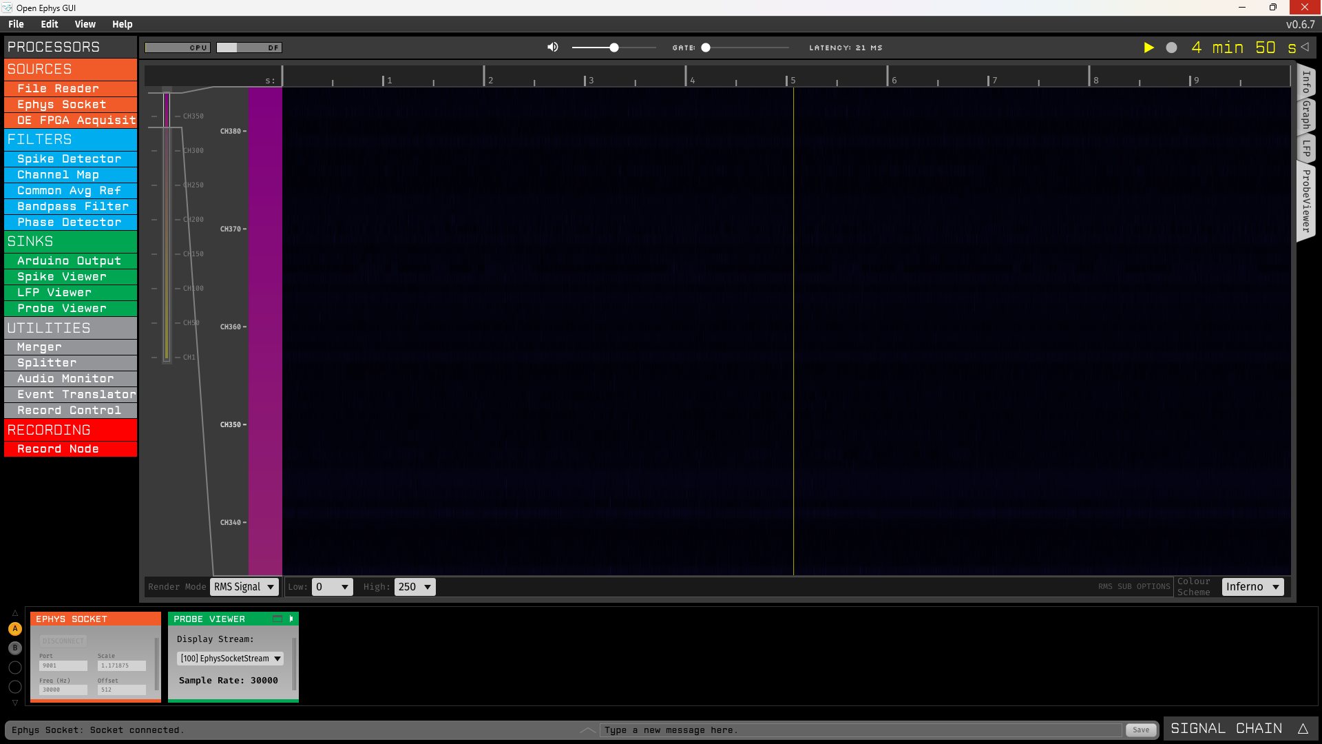
Configure processors to visualize spike data
Drag the source processor Ephys Socket from the Processor list and drop it
onto the Signal Chain area, followed by the sink processor Probe Viewer.
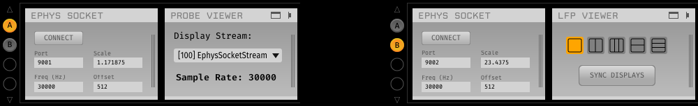
Ephys data in the Open Ephys GUI is represented using floating point values in units
of microvolts. Data coming from Bonsai will need to be converted to microvolts in
order to plot properly within the GUI. To do this, the Ephys Socket processor
provides the "Scale" and "Offset" values:
\(Output\, (uV)= Scale * (Input - Offset)\)
In this tutorial we used the following values:
- Scale: 1.171875.The NeuropixelsV1e device on NeuropixelsV1e headstage has a step size of 1.2e6/1024/gain μV/bit and the AP Gain was configured at 1000.
- Offset: 512. The NeuropixelsV1e device outputs offset-binary encoded signed 10-bit data, so 512 corresponds to 0 volts.
Tip
The appropriate scale and offset values for any headstage can be found by navigating to its respective Data Frame page. For example, those values for the Neuropixels 1.0 device are available on the NeuropixelsV1DataFrame page.
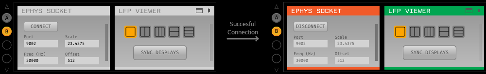
After configuring Ephys Socket processor, press the "Connect" button to
establish a connection with the SpikeServer running in Bonsai.
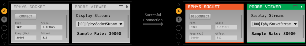
Open the visualizer by clicking the “tab” button in the upper right of the Probe Viewer. Click the
play button in the Control Panel at the top of the GUI to begin data acquisition.
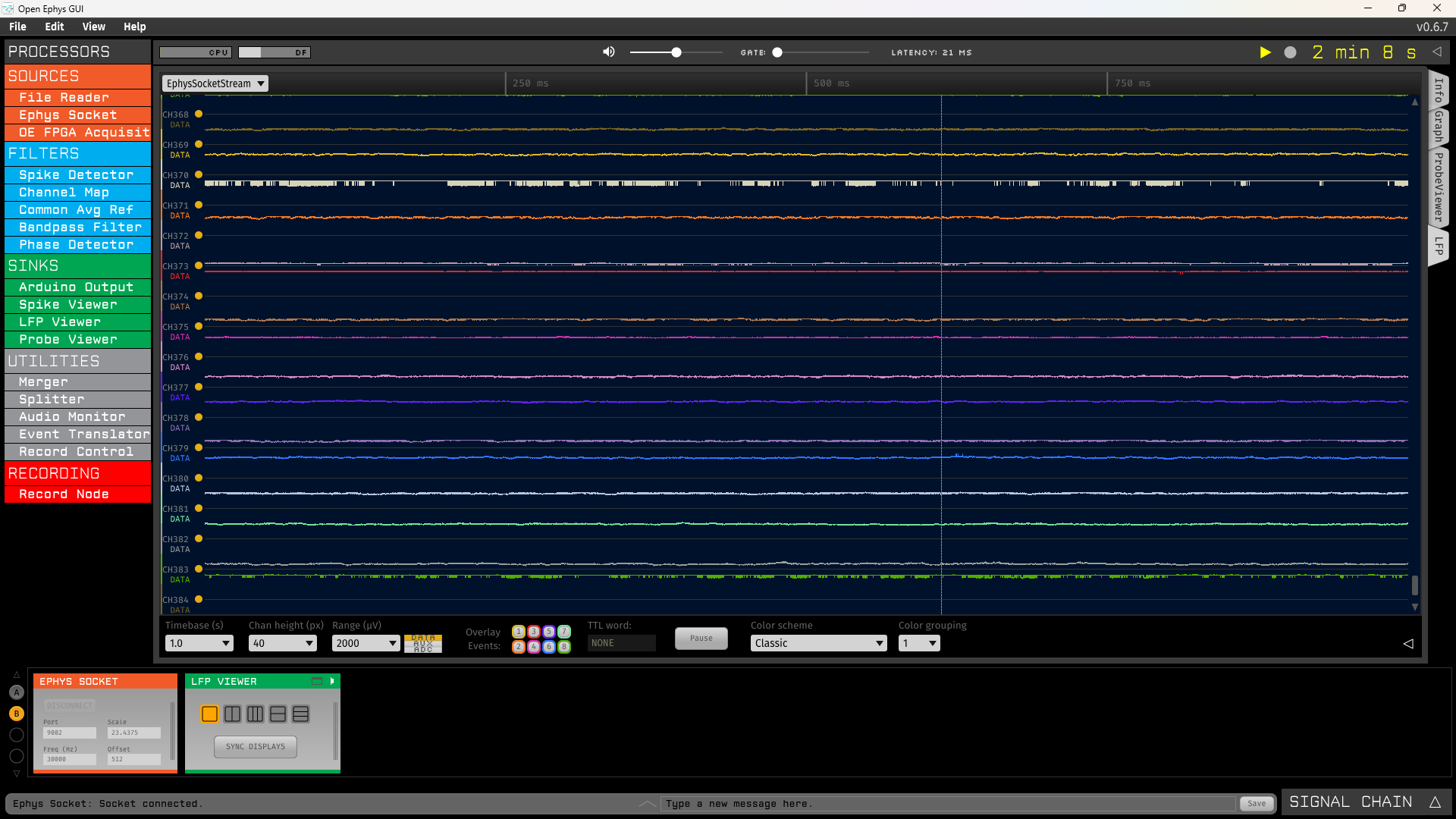
Configure processors to visualize LFP data
Drag the source processor Ephys Socket from the Processor list and drop it
onto the Signal Chain area, followed by the sink processor LFP Viewer.
configure the Ephys Socket processor "Scale" and "Offset" to convert incoming
data to microvolts. In this tutorial we have used the following values for
these parameters:
- Scale: 23.4375. The NeuropixelsV1e device on NeuropixelsV1e headstage has a least significant bit of 1.2e6/1024/gain μV/bit and the LFP Gain was configured at 50.
- Offset: 512. The NeuropixelsV1e device outputs offset-binary encoded signed 10-bit data, so 512 corresponds to 0 volts.
After configuring Ephys Socket processor, press the "Connect" button to
establish a connection with the LfpServer running in Bonsai.
Open the visualizer by clicking the “tab” button in the upper right of the LFP Viewer. Click the play button in the Control Panel at the top of the GUI to
begin data acquisition.
Tip
You can read more about using each specific plugins used in this tutorial by reading their documentation:
Video Summary
Below is video summary of this tutorial showing how this works: