Mounting and Connecting#
Mounting#
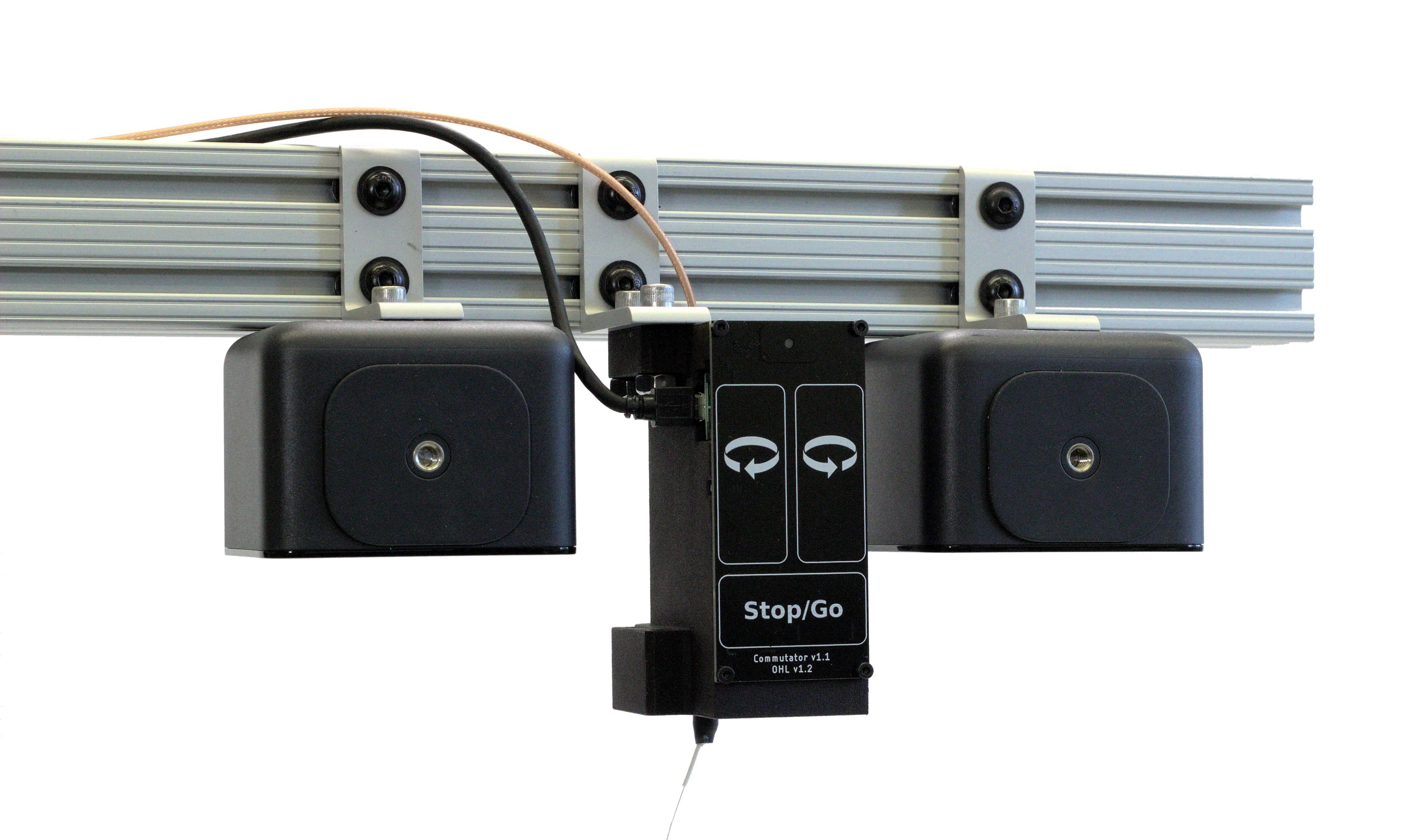
The commutator has several holes that can be used to mount it on 80/20 aluminum extrusion using t-nuts or a standard mechanical breadboard. For example:
For custom mounting solutions, you can find the 3D mCAD files in the following repos:
For any commutator with a Teensy (i.e. if your commutator has a Micro-USB port)
For any commutator with an RP2040 (i.e. if your commutator as a USB-C port)
These files can be be opened and the design dimensions can be measured using mCAD software that supports either SolidWorks files (e.g. eDrawings) or STL files (e.g, FreeCAD). Both file types are available in the repositories linked above.
More information on the best location to mount the commutator is available on the Tether Management & Headstage Counterweight page.
Connecting#
1. USB Connector
The commutator receives power and communicates to the PC over USB through this interconnect. Newer commutators use USB-C. Older commutators use Micro-USB.
2. Top SMA Connector
The commutator’s stator connects to a stationary data acquisition device that has a coaxial port (e.g. Miniscope DAQ or ONIX breakout board) through this SMA interconnect.
3. Bottom SMA Connector
The commutator’s rotor connects to a freely moving animal headstage that has a coaxial connector through this SMA interconnect.

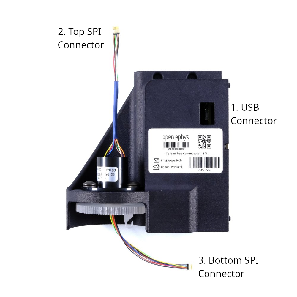
1. USB Connector
The commutator receives power and communicates to the PC over USB through this interconnect. Newer commutators use USB-C. Older commutators use Micro-USB.
2. Top SPI Connector
The commutator’s stator connects to a stationary data acquisition device that has a SPI port (e.g. the Open Ephys Acquisition Board) through this 12-pin Omnetics PZN-12 interconnect.
3. Bottom SPI Connector
The commutator’s rotor connects to a freely moving animal headstage that has a SPI connector through this 12-pin Omnetics PZN-12 interconnect.
1. USB Connector
The commutator receives power and communicates to the PC over USB through this interconnect. Newer commutators use USB-C. Older commutators use Micro-USB.
2. Top Center SMA Connector
The commutator’s top center SMA connector connects to a stationary data acquisition device that has a coaxial port (e.g. Miniscope DAQ or ONIX breakout board) through this SMA interconnect. It has electrical continuity with 4. Bottom Center SMA Connector.
3. Top Off-Center SMA Connector
The commutator’s top off-center SMA connector connects to a stationary data acquisition device that has a coaxial port (e.g. Miniscope DAQ or ONIX breakout board) through this SMA interconnect. It has electrical continuity with 5. Bottom Off-Center SMA Connector.
4. Bottom Center SMA Connector
The commutator’s bottom center SMA connector connects to a freely moving animal headstage that has a coaxial connector through this SMA interconnect. It has electrical continuity with 2. Top Center SMA Connector.
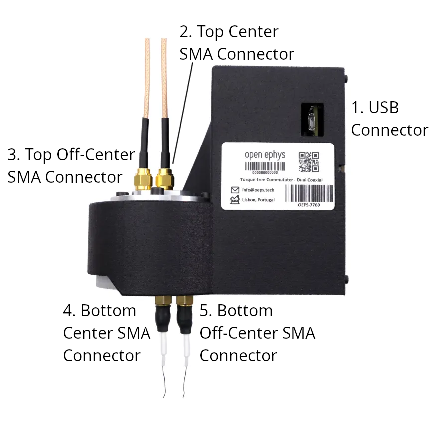
5. Bottom Off-Center SMA Connector
The commutator’s bottom off-center SMA connector connects to a freely moving animal headstage that has a coaxial connector through this SMA interconnect. It has electrical continuity with 3. Top Off-Center SMA Connector.
Tip
Some USB cables only supply power. Confirm your USB cable transfers both power and digital signals.
Source USB and coax cables from a reputable vendor such as Digikey, Mouser, or Open Ephys.
Source your tether from Open Ephys or make your own.
For animal behavior experiments, manage cables such that they do not interfere with the tether when the animal moves.