Making Coaxial Tethers#
ONIX headstages communicate with host hardware using a 50-Ohm coaxial cable. Because these tethers only have two conductors, replacing them or making tethers of custom lengths is quite simple. This page describes methods for creating light and flexible coaxial headstage tethers.
Which Coaxial Cable?#
Any suitable 50-Ohm coaxial cable can be used to make a tether. These instructions use Axon Cable PCX40K10AK. The cable should be light, flexible (silicone or thin FEP insulation), thin (less than 1 mm in diameter), and made by a reputable supplier that can supply information on the cable’s electrical characteristics. Most important are its DC Resistance and RF Loss in the 1 GHz regime.
Note
Although the actual quantities matter, and smaller values are better, the major hurdle is simply finding a supplier that will clearly characterize them as this an indication of quality. We have used cables from Axon Cable and cooner wire with good results.
- DC Resistance:
For DC signals, resistance is proportional to the inner conductor’s resistivity and length and inversely proportional to its cross-sectional area. The larger the DC resistance of the cable, the larger the voltage drop across the cable, which requires increased compensation at the voltage source. DC resistance is a strict function of the cable’s size and thinner, longer cables will have a higher resistance than thicker, shorter cables.
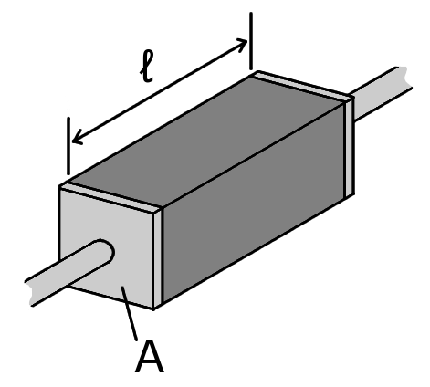
A piece of resistive material with electrical contacts on both ends. https://commons.wikimedia.org/w/index.php?curid=1699802#
- RF Loss:
For radio-frequency signals transmitted in coaxial cables, frequency-dependent resistance (“loss”) is determined by the skin effect rather than conductor cross sectional area. Higher loss at a particular frequency will limit the length of cable over which signals using that frequency band can be reliably sent and received. Minimizing RF loss while maintaing uniform characteristic impedance characteristics is and engineering challenge and requires precision manufacturing.

For alternating current, the current density decreases exponentially from the surface towards the inside. https://commons.wikimedia.org/w/index.php?curid=4453931#
Assembly Guide#
Headstage Side#
- Required Tools and Materials
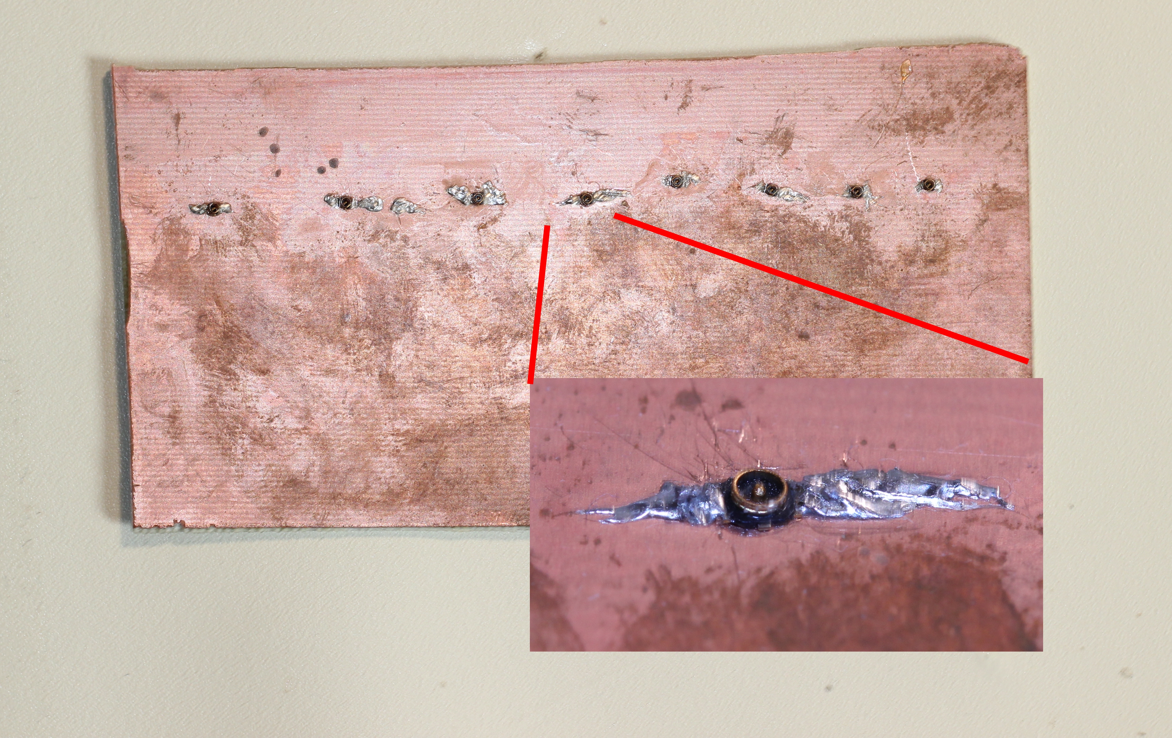
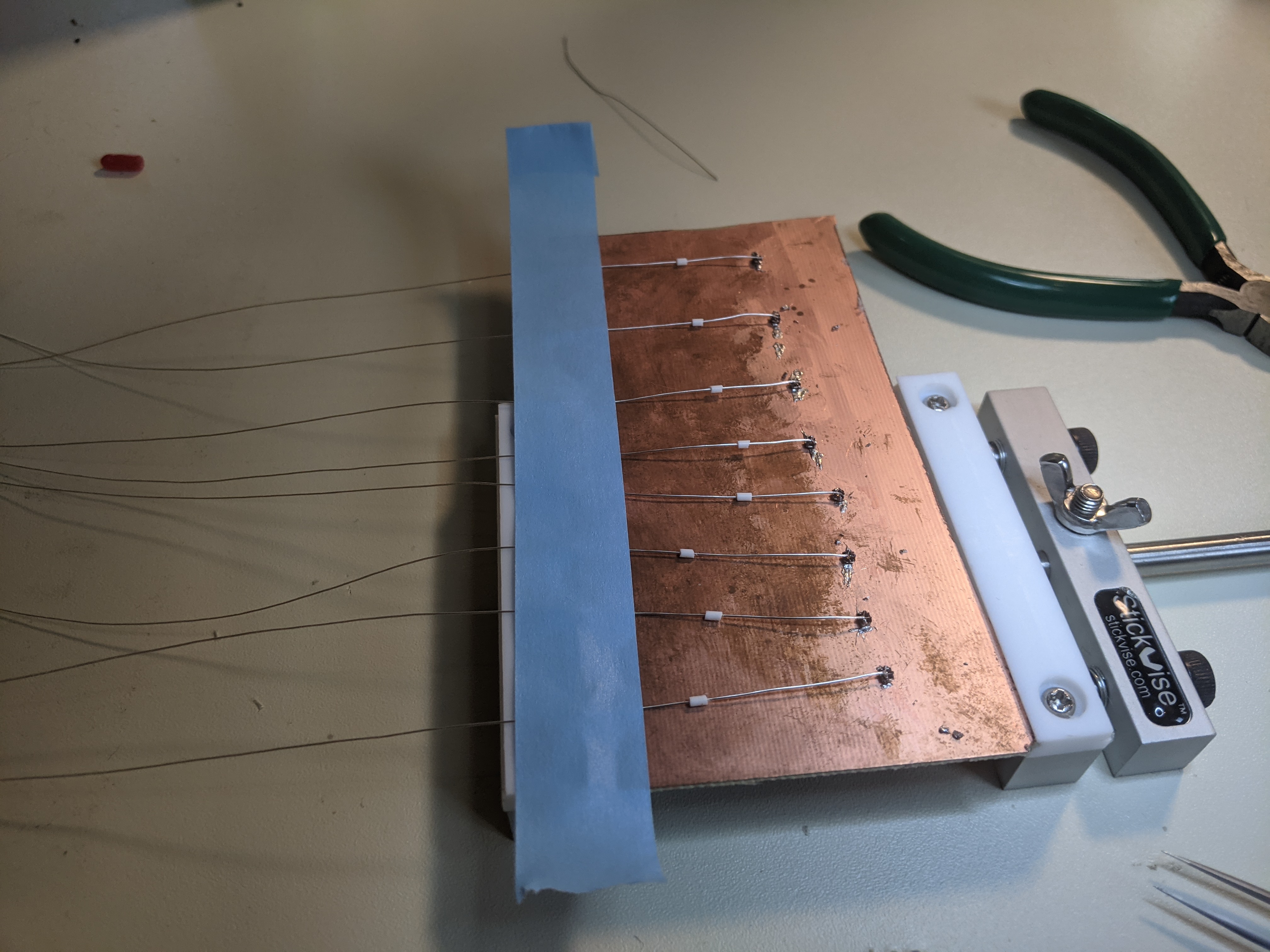
Solder jig: A copper-clad board with X.FL connectors (X.FL-R-SMT-1(80)) soldered to it to that hold X.FL sockets in place during soldering.
5-minute epoxy
Small and sharp wire cutters
Fine forceps (e.g. Dumont #5) for stripping the cable
Soldering iron with a fine tip (0.2 mm diameter or smaller) and accurate temperature control
Fine solder (0.5 mm or thinner diameter)
No clean flux paste (e.g MG chemicals 8341)
A microscope is highly recommended for soldering and manipulation of stripped cable segments.
- Cable Components
Coaxial cable segment (these instructions uses Axon Cable PCX40K10AK)
Hirose X.FL-PR-SMT1-2(80) X.FL coaxial socket
2 mm segment of 1.5 mm OD, 0.5 mm ID silicone tubing for strain relief. The easiest and cheapest way to get this is by striping the silicon jacket from a 24 AWG flexible hookup wire.
Press X.FL sockets onto the X.FL connectors on the solder jig. We’ve found that this is the most convenient method for holding these tiny pieces in place during soldering and gluing.
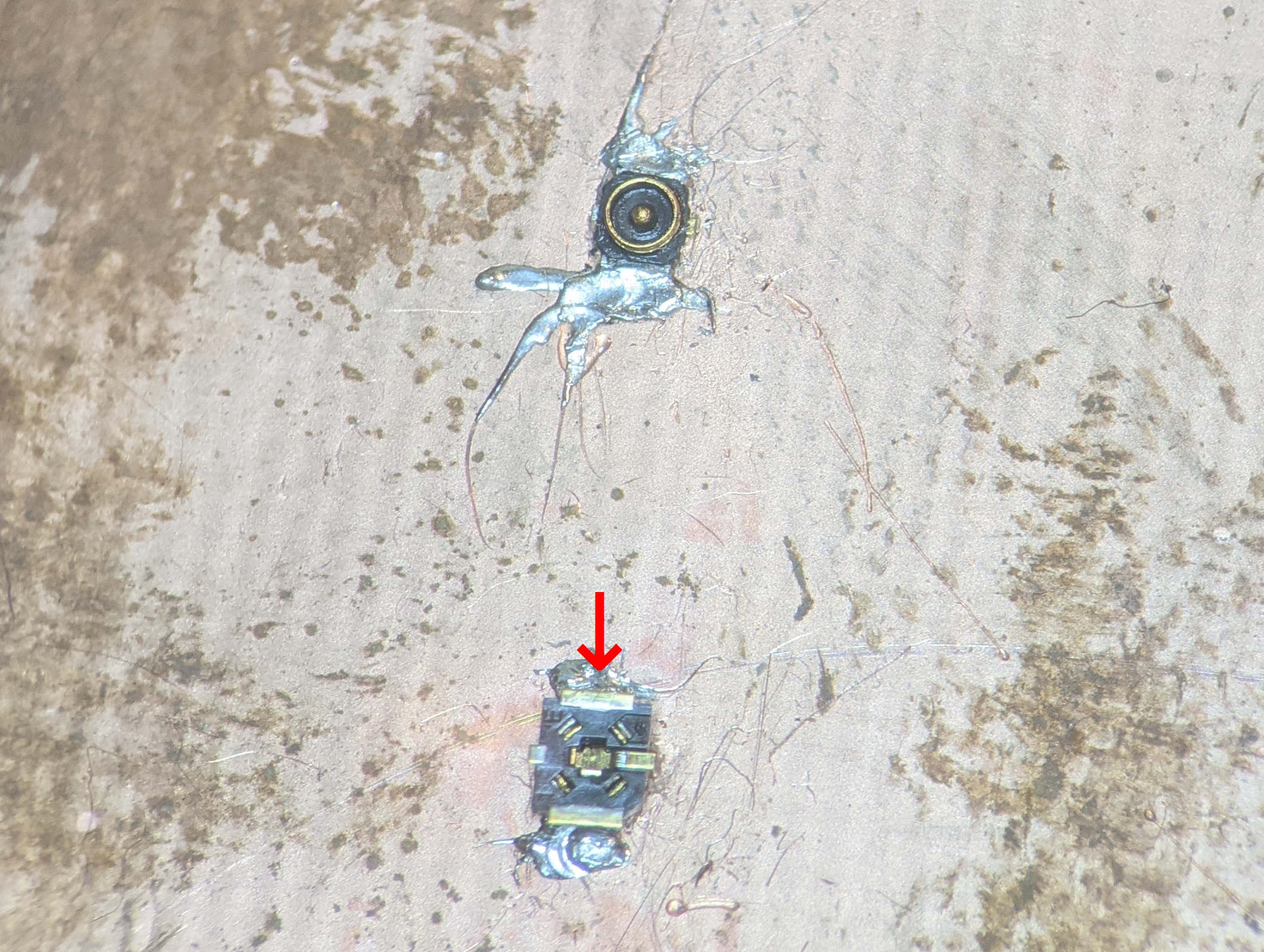
Set the soldering iron to ~260 C. Using a fine soldering iron tip (~0.2 mm or smaller), melt the plastic on the back side of the X.FL sockets to cover the holes in the plastic. This is required to prevent epoxy applied in later steps from getting into the mating surfaces of the connectors.
Return the iron to soldering temperature (~370 C). Apply a dab of flux the contacts on the X.FL socket. Tin the two outer ground contacts on the socket along with the center pin connector.
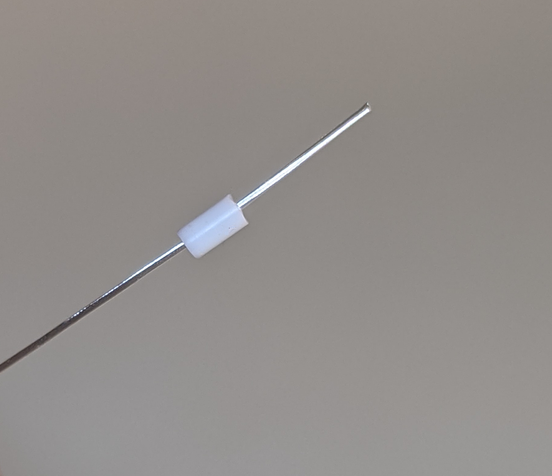
Slide the 2 mm silicone tube over the end of the cable segment and push away from the tip for later use.
Use the forceps to strip about 4-5 mm of the outer jacket from one end of the coaxial cable segment. This can be done by pinching the tip of the cable with the forceps and pulling it. This step may require some practice to get right.

Note
If you are not able to cleanly remove the outer insulation from the coaxial cable on the first try, just cut the tip off and start over. Clean insulaiton removal makes everything easier.
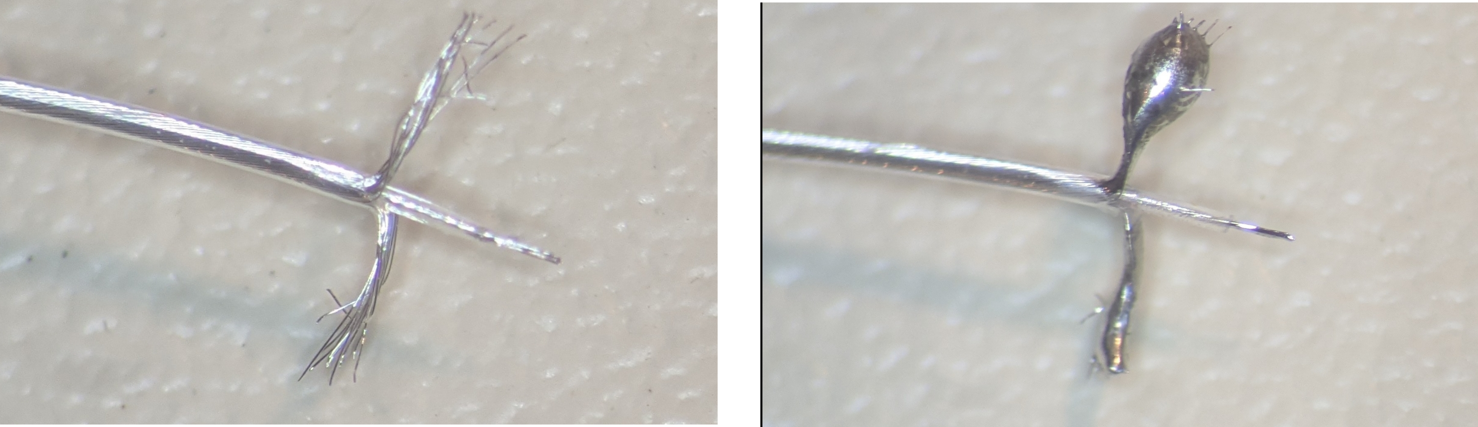
Split the outer conductors into two bundles that pushed to either side of the cable. Use the forceps to strip the inner conductor in the same way as before. Tin the two outer-conductor bundles and the inner conductor.
Important
Ensure that there are no stray wires after this process as they can can cause shorts when the cable is soldered to the socket.
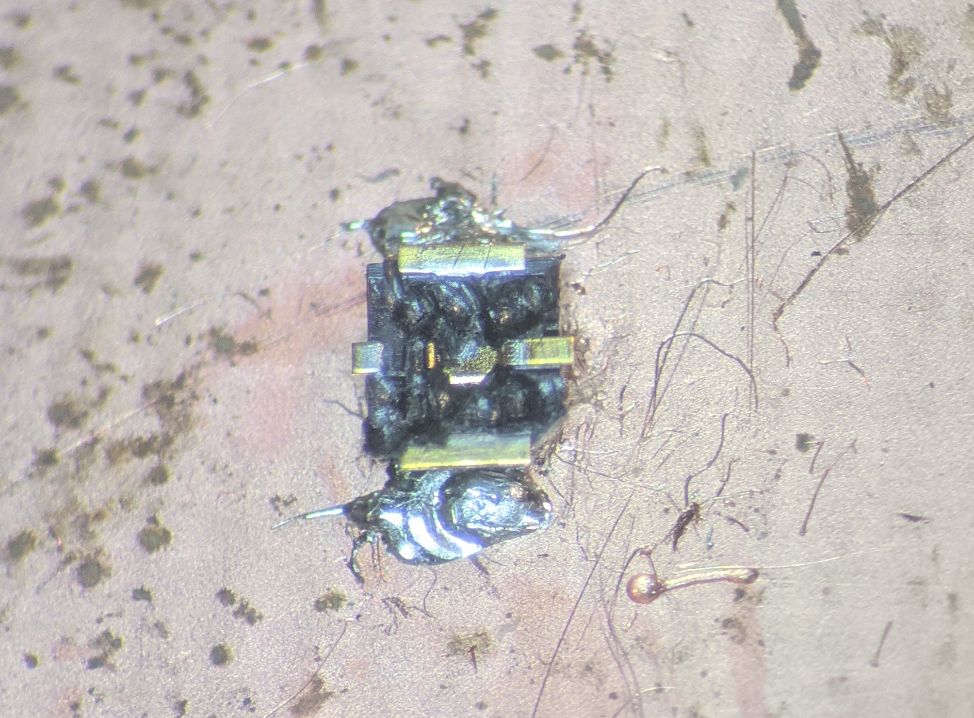
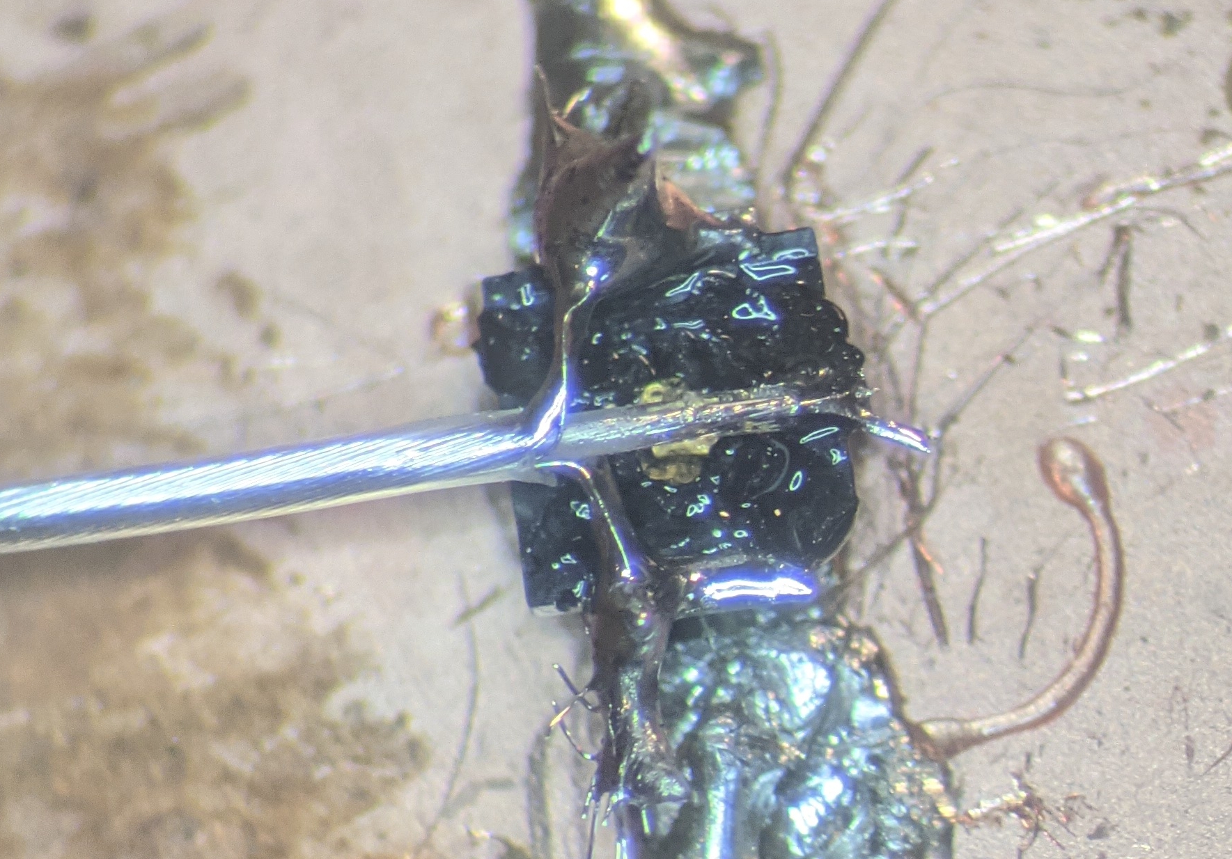
Solder the cable to the X.FL socket. Ensure that the outer connectors are not making contact with the inner conductor, e.g. by being placed directly over the center of the X.FL socket.
Trim the lead excess using the small wire cutters.

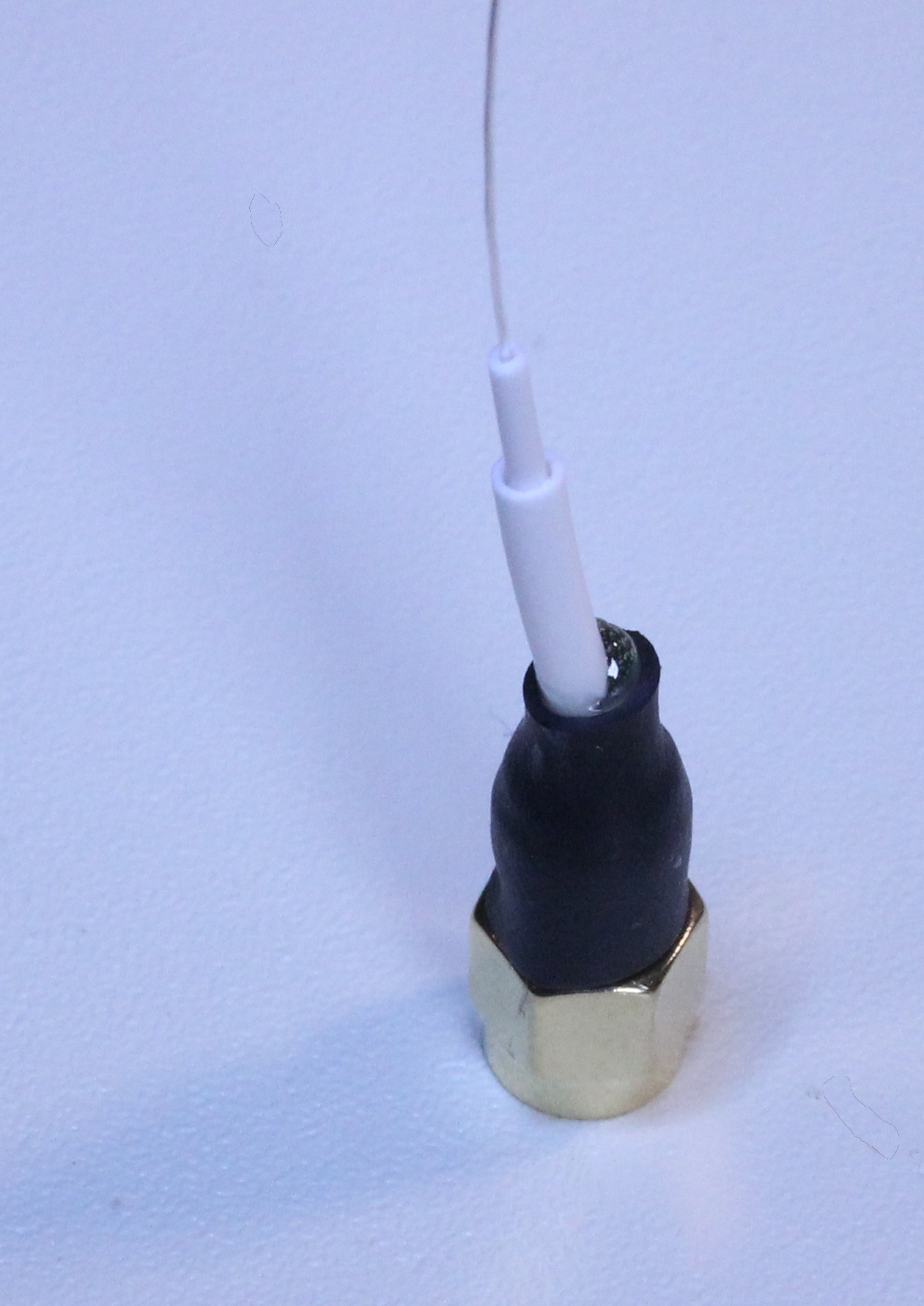
Mix and apply 5-minute epoxy to over the back of the X.FL socket. The epoxy should completely cover the solder joint and extend ~1 mm onto the cable itself.
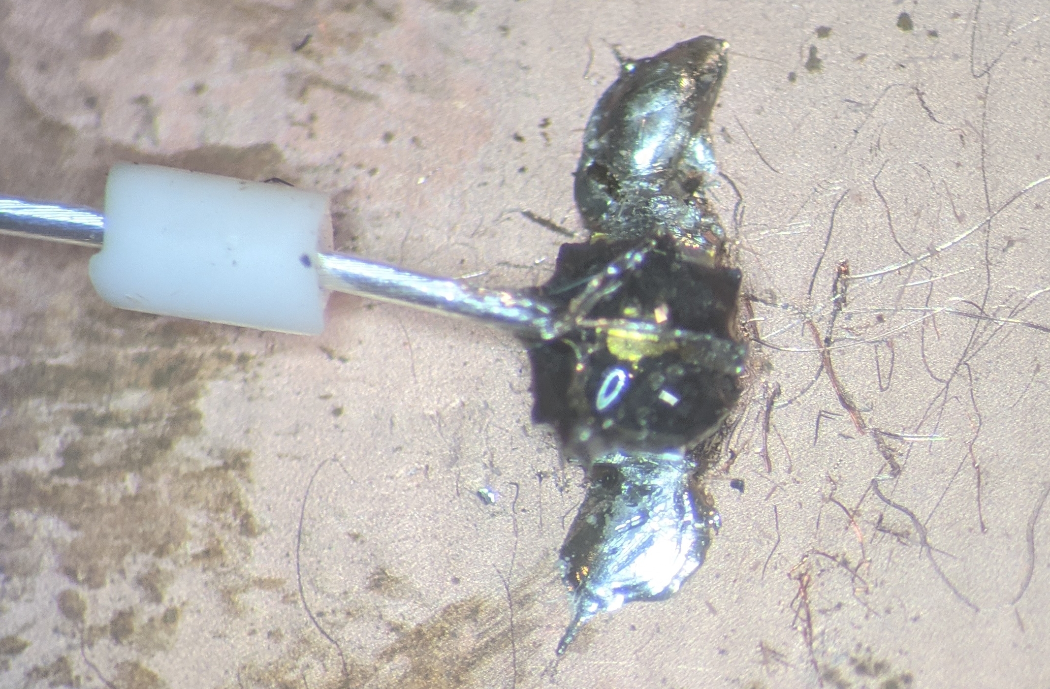
Before the epoxy begins to cure, slide the 2 mm silicone tubing sement into the epoxy, rotating a bit to ensure the inner portion and outer edge of the silicone tube get a layer of epoxy.
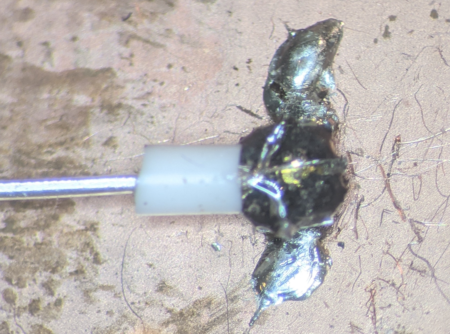
Allow the epoxy to cure and then remove the completed assembly from the jig.
Warning
If expoxy has leaked between the X.FL contacts and bonded them together, then the socket’s back was not properly melted in step 2, and cable probably will not work.
Tip
Typically, the jig will have multiple X.FL connectors so that several tethers to be made in parallel.
Host/Commutator Side#
- Required Tools and Materials
5-minute epoxy (Bob Smith Industries brand works well)
Small wire cutters
Fine forceps for stripping the cable
Soldering iron with a fine tip and accurate temperature control
Fine solder (0.5 mm or thinner diameter)
A microscope is highly recommended for soldering and manipulation of stripped cable segments.
Hot air gun or hot air rework station.
- Cable Components
Coaxial cable segment
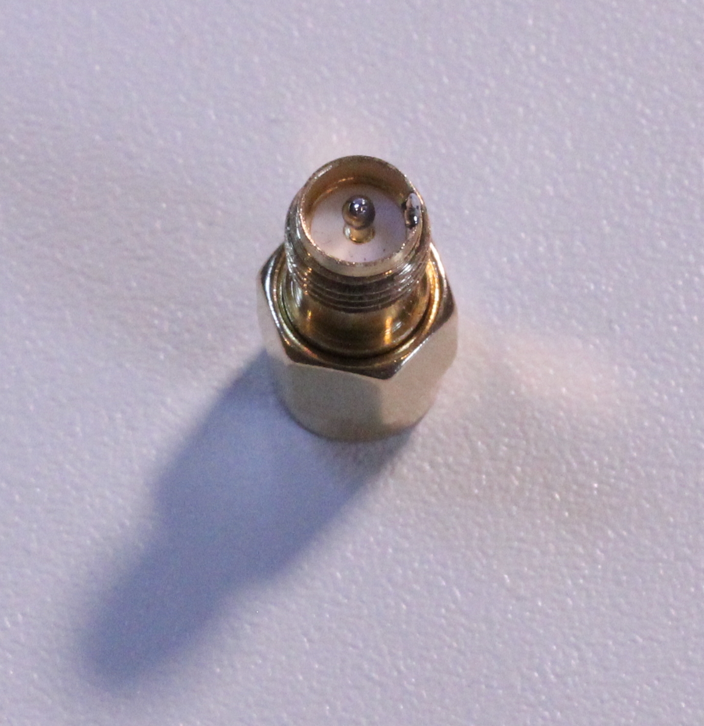
SMA plug to reverse-polarity SMA plug adapter
20 mm segment of 1.5 mm OD, 0.5 mm ID silicone tubing for strain relief. The easiest and cheapest way to get this is by striping the silicon jacket from a 24 AWG flexible hookup wire.
15 mm segment of 2.5 mm OD, 1.5 mm ID silicone tubing for strain relief. The easiest and cheapest way to get this is by striping the silicon jacket from a 20 AWG flexible hookup wire.
12 mm segment of 6.35 mm OD, 3:1 shrink ratio, adhesive lined heat-shrink tubing for strain relief. We have found that NTE 47-23248-BK works well.

Place the SMA plug adapter on the work surface with the reverse polarity end pointing up. It can be helpful to screw the adapter into a mating SMA receptacle to hold it still during soldering. Tin the inner conductor and a portion of the outer edge of SMA adapter.
Slip all three strain relief tubes over the coaxial cable.
Use the fine forceps to pinch and strip about 5mm of the outer jacket from the from the end of the cable.
Note
If you are not able to cleanly remove the outer insulation from the coaxial cable on the first try, just cut the tip off and start over. Clean insulaiton removal makes everything easier.
Separate the outer conductor wires into a single bundle and strip the insulation from the inner conductor.
Tin the outer and inner conductors.
Important
Ensure that there are no stray wires after this process as they can can cause shorts when the cable is soldered to the socket.
Solder the cable onto the SMA adapter
Mix and apply 5-minute epoxy to the well provided by the coax adapter to completely cover the solder joint. Put enough expoxy in the well such that it rises well above the edge and his held in place due to surface tension.
Before the epoxy cures, move the 20 mm segment into the solder blob. Move up and down to ensure that the bottom portion of the silicon tube is covered in epoxy. Repeat this process for the 15 mm segment.
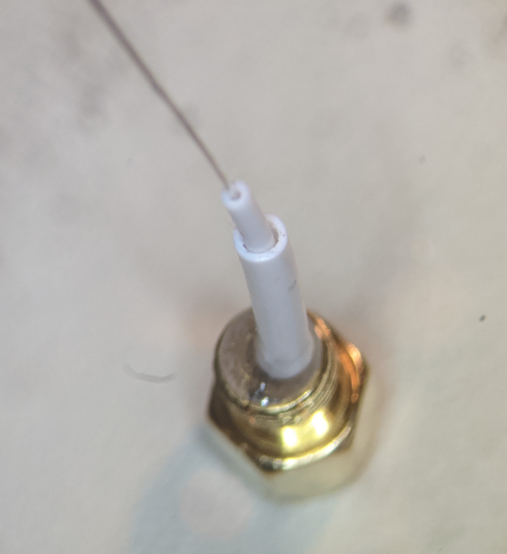
Slip the final heat shrink tube over the base of the SMA adapter. Wait for the epoxy to cure.

Set the the hot air gung to ~250 C and use it to activate the heat shrink tubing starting at the base of the connector and working up toward the top. The seal is complete when the adhesive lining begins to come out of the top of the heatshrink tubing.