Trigger recordings with a hardware digital signal#
Note
This tutorial builds on the Quick Start Guide and previous tutorials.
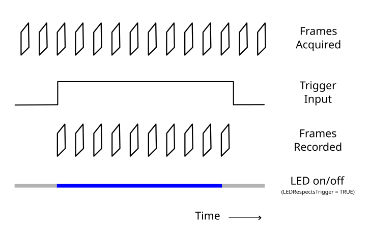
The Miniscope DAQ Digital Input ports receives 3.3V or 5V level digital inputs. That signal can be used to gate recording to file. After following this tutorial, the user will be able to record both image and orientation data to file following a hardware trigger signal. In this workflow, recording to file is initiated at the each rising edge and terminated at each falling edge of digital input 0, as depicted below. The LED on/off state can optionally follow the trigger.


Workflow Description#
Miniscope Data Publishing

The UclaMiniscopeV4 node output is connected to a BehaviorSubject named MiniscopeDataFrame which publishes the stream so it can be reused in multiple parts of the workflow. This branch is used to visualize the Image and Quaternion members and to provide orientation data to the Commutator group workflow.
Trigger Logic

On a second branch, the same MiniscopeDataFrame is saved to file based
on the state of the DigitalIn member, which corresponds to the status of
the DAQ’s digital input ports. A Condition node named
TriggerAsserted contains logic checking if a rising edge (LOW → HIGH
transition) has occurred on digital input 0. The condition node fires once
per rising edge as determined the logic in the subworkflow:

When a rising edge is detected, a SelectMany operator named
ChunkData subscribes to the MiniscopeDataFrame data stream to begin
recording. The TakeWhile operator ensures that frames are passed
downstream only while digital input 0 remains HIGH. When digital input 0
goes LOW, the recording chunk ends:

TakeWhile can be inspected by double-clicking when the workflow is not running.
This mechanism creates one recording session per hardware trigger pulse. After each pulse, the workflow resets using the Repeat operator so it is ready for the next trigger event. Within each trigger-defined recording session, the Image, FrameNumber and Quaternion data are written to file as explained in previous tutorials: one video and one csv file are generated per trigger pulse.
Note
This workflow can just as easily be configured to trigger on Digital Input 1 instead. Simply change the Value property of the HasFlag node in the “TriggerAsserted” Condition subworkflow and the HasFlag node in the TakeWhile subworkflow to “DigitalIn1”.
Configure the Hardware#
Additional required components: external hardware with 0-5V digital output, SMA-ended cable
Configure the hardware as in the Quick Start Guide or as in the Automate tether commutation using 3D orientation data tutorial if you are using an Open Ephys Commutator.
Additionally, connect a 0-3.3V or 0-5V trigger source to the Dig. In 0 port using the SMA cable or a suitable adapter such as a BNC-SMA adapter.
Get Started in Bonsai#
No additional packages besides the ones listed in the Quick Start Guide and previous tutorials are required.
Operate the Workflow#
Set the
UCLAMiniscopeV4operator’sIndexproperty to the value that corresponds to the index of your miniscope.If using a commutator, set the COM port associated with your commutator in the workflow. If not using a commutator, delete the nodes corresponding to the commutation.
Set the
UCLAMiniscopeV4operator’sLEDRespectsTriggerproperty to True if you intend to use the LED only during the triggered recording. This can help reduce photobleaching during long experimental sessions with multiple triggered recordings, but means the LED will be off during acquisition periods that are not being recorded to file. To be able to monitor the brain activity during acquisition, toggle this property to False.Run the workflow and verify that images that are visualized by clicking “ChunkData” are emitted only when digital input 0 is HIGH, and that the LED behaves according to the previous step