
Troubleshooting Guide#
Here is a guide to help you troubleshoot common error scenarios that can occur when using the Miniscope system. It is focused on the UCLA Miniscope v4 with the Open Ephys Miniscope DAQ, and Bonsai usage in Windows.
If issues persist after following this guide, the scenario you encountered is not in this guide, or you believe your Miniscope and/or DAQ needs repair, please reach out as detailed under How to ask for help.
General recommendations#
Keep the acquisition software up to date with the latest version.
Keep the Miniscope DAQ firmware up to date with the latest version.
Keep an eye out for warnings and errors in the software during operation.
Configure the USB settings to avoid suspension due to power management, which interferes with USB communication.
Initial troubleshooting steps#
1. Check the hardware USB connection#
Always use a USB 3.0-compatible port on your computer with the high-speed USB cable provided. USB 3.0-compatible ports are usually indicated by a blue color. Ensure you establish a reliable USB connection by connecting directly to the port instead of through a hub or extension.
You can try a different USB 3.0 port and test with a different USB cable, as faulty cables are a common cause of connection problems.
All three indicator lights on the DAQ and the red LED on the miniscope body itself must be continuously on.
USB Configuration#
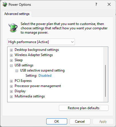
The Miniscope DAQ works via USB, and the PC’s power management, on both laptops and desktops, can interfere with USB communication. This can be experienced as a sudden interruption during an otherwise stable period of acquisition that can be traced back to USB communication errors and not a hardware disconnection. Always ensure that the USB settings are configured to avoid suspension.
On Windows desktops, go to Control Panel > Hardware and Sound > Power
Options > Edit Plan Settings, and into the Advanced Power Settings.
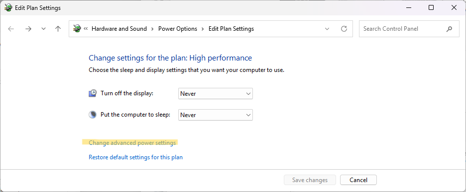
Change the settings for the power plan that you are using to ensure that the USB selective suspend setting is Disabled.
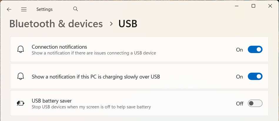
On Windows laptops, a similar option to disable the USB battery saver is
available under Settings > Bluetooth & Devices > USB
2. Check that the DAQ is recognized properly by the Operating System#
After following step 1, the DAQ and Miniscope should be recognized by the
Operating System. Go to Start Menu > Settings > Devices > Bluetooth &
other devices and check that the DAQ and Miniscope are listed as Connected to
USB3.0, with no additional warnings.
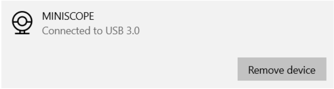
If not, refer to Connecting the Hardware for additional details.
3. Check your cable, coaxial tether and connectors#
Always ensure that all connectors on the DAQ, miniscope and commutator (if using one) are fully seated. Inspect the USB cable, the coaxial tether and its connector, and the miniscope connector for any signs of damage, debris or wear. Test your coaxial tether for shorts.
Even if a USB cable shows no visible damage, it can still cause issues, especially when flashing the DAQ. If problems persist, try a different USB cable, preferably the one supplied with the DAQ.
Although we generally recommend keeping the Miniscope connected to the coax tether, the U.FL connection should feel firm and click into place when connected. If it does not, the tether’s U.FL connector may be bent or damaged, which can prevent a reliable connection.
4. Review order of operations#
After disconnecting all components and closing the software, reconnect the system in the following order: first, plug the coaxial tether into the miniscope. Next, connect the miniscope to the DAQ. Finally, connect the DAQ to your computer. Only once all three lights on the DAQ and the red LED on the miniscope are on should you open the software.
Refer to Connecting the Hardware for additional details.
Some error scenarios and solutions#
Horizontal stripes#
Connection errors occur when the DAQ detects a powered device but is unable to receive a continuous signal from it. Problems like dropped frames, inconsistent frame rate and stripe artifacts indicate that there is a connection issue.
This typically indicates a communication problem between the miniscope and the DAQ.
Horizontal stripes appear when there is a mismatch between frames coming to the DAQ. These issues are commonly caused by connectors that are not fully seated, a damaged coaxial tether, or an unstable USB connection.
To resolve this, disconnect and reconnect the miniscope and restart the software.
Follow the Initial troubleshooting steps above to identify and resolve the source of the connection issue.
Note
In case this happens during acquisition in the middle of an experiment, the affected frames can sometimes be recovered and corrected offline by shifting the affected image buffers back into place. You might want to try using the Stripe Cleaner tool kindly provided by the Cai Lab or this post-hoc correction tool that can help fix this buffer mismatch artifact in some cases.
Horizontal banding artifacts#
When powered via USB, the DAQ can only supply 5V. Depending on your setup and settings such as cable length, type of cable, commutation and LED brightness, the USB supply may not provide sufficient power to operate the miniscope reliably.
Horizontal banding artifacts can occur due to insufficient or unstable power delivery and are typically more pronounced at higher LED intensity settings. You can check that no other devices are drawing significant power from the same USB ports.
This can be resolved by externally powering the DAQ. Refer to the External Power section for instructions on how to connect and use an external power source, while carefully monitoring the voltage at the miniscope.
Error messages#
This table can help you understand and troubleshoot error messages from the OpenEphys.Miniscope Bonsai package.
Error message |
Issue and reason |
Resolution |
|---|---|---|
Stopped receiving frames |
No frames are being received by the system. This error points to a communication failure due to either a USB disconnection and/or a detachment of the coaxial tether. |
Follow the Initial troubleshooting steps above to identify and resolve the source of the connection issue. |
Invalid quaternion value |
Frames are still being received but the quaternion data is invalid or corrupted. This error indicates an intermittent loss of communication, most likely due to a temporary coaxial tether disconnection. While data acquisition resumed once connectivity was restored, orientation data was lost. |
Follow the Initial troubleshooting steps above to identify and resolve the source of the connection issue. |
Invalid Miniscope DAQ index |
The specified Miniscope index is out of range for the number of connected devices. This occurs when the index does not correspond to any detected miniscope. |
Make sure the |
Unsupported DAQ Firmware |
A Miniscope DAQ running firmware prior to version 1.5.0 has been detected. |
Update the DAQ Firmware to the latest version. Refer to the Firmware Update section of this documentation. |
EWL focus not functioning#
Inspect your PCB and EWL connection
Check whether the flex PCB is bent or damaged near the EWL and verify that the objective module is properly tightened. An impact to the miniscope can cause the PCB to move slightly, preventing proper contact between the EWL and the PCB. Ensure the screws are secure and that the circular contact pads on the PCB are correctly seated within the objective module and making firm contact with the EWL.
EWL driver
The focus issue can be related to the power switch/driver responsible for controlling the EWL. If this component isn’t functioning properly, it can cause the focus to stop working, produce vertical line artifacts, and in some cases heat the PCB. This failure is typically caused by a crack or physical damage to the component.
Such damage is usually not visible to the naked eye and requires inspection under a microscope. Inspect the component to look for any cracks or signs of damage, particularly around the corners to check for a chipped edge or fine fracture lines. This component is located on the outside of the PCB, on the LED PCB side, circled in red in the image below. It is on the opposite side of the miniscope from the coaxial tether connector. Also check if this area of the PCB is generating noticeable heat.
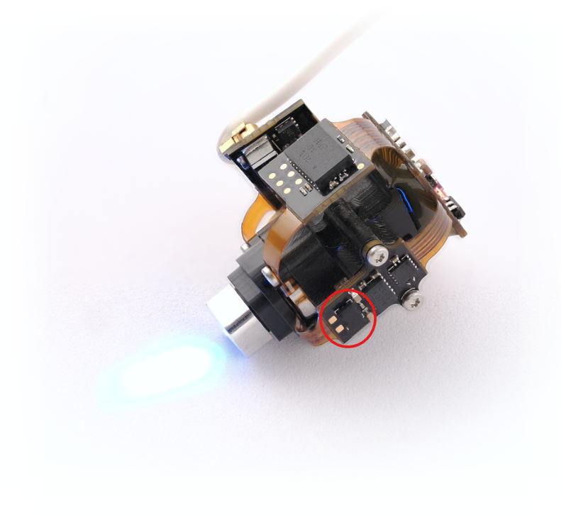
If the component is cracked or damaged, the recommended solution is to replace the PCB. You can follow our Disassembly for PCB Replacement guide and Assembling the UCLA Miniscope V4 guide for step-by-step instructions to complete the replacement. Alternatively, the component can sometimes be replaced without changing the entire PCB. For more details, contact us about our repair services.
Radial pixelation artifacts#
Radial pixelation artifacts indicate a defect on the PCB. This issue is commonly caused by damage to the flex PCB between the image sensor and the serializer, which leads to corrupted or missing bits in the pixel data stream.
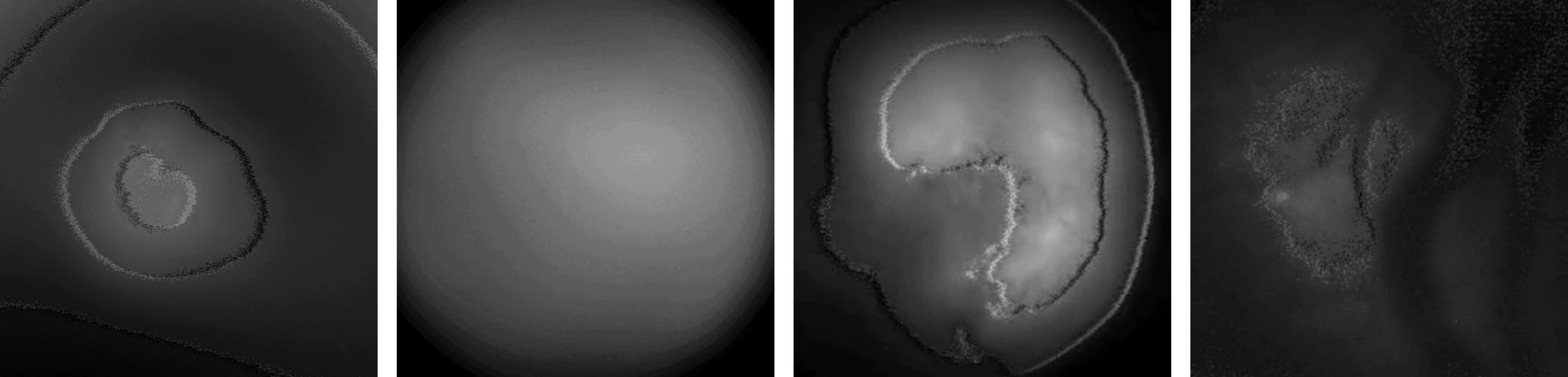
The solution for this is to replace the PCB. You can follow our Disassembly for PCB Replacement guide and Assembling the UCLA Miniscope V4 guide for step-by-step instructions to complete the replacement.
Excess power#
When using external power, we recommend using a variable power supply and closely monitoring the voltage delivered to the miniscope to avoid damage. Refer to the External Power section for details.
Supplying voltage to the Miniscope DAQ that results in exceeding the miniscope operating voltage can damage the device. The maximum supply voltage will depend on your tether length and configuration. In such cases, the miniscope may fail to connect or may not function properly. If this occurs, the PCB is likely damaged and requires replacement.
You can follow our Disassembly for PCB Replacement guide and Assembling the UCLA Miniscope V4 guide for step-by-step instructions to complete the replacement.
The DAQ itself is powered via USB even when external power is connected, so it should not be affected or damaged by higher voltages applied to the external power input.
DAQ Data Link light not turning on or flickering#
If the Data Link LED flickers very rapidly, the data transmitted over the coaxial tether may be corrupted, preventing the DAQ from establishing a connection. This is usually caused by a damaged L13 inductor (noise filter) on the DAQ PCB, most often due to a short circuit in the coaxial tether.
Open the DAQ case and inspect the PCB, paying particular attention to the L13 inductor and the area close to the coaxial tether connector. Sometimes, the damage can be seen by eye as a burn mark or discoloration.
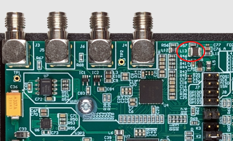
If the L13 inductor is damaged, replacing it should resolve the issue. If you have the appropriate tools and soldering experience, you should be able to replace it yourself.
Note
Before connecting any coaxial tether to a DAQ, always test it for shorts. A faulty tether can damage the L13 inductor and cause the same issue again.
Damage on the coaxial tether#
If your tether shows any signs of damage, such as cuts, kinks, or chew marks, use a multimeter to verify continuity between the connector pins and confirm that there are no shorts before connecting it to the DAQ.
How to ask for help#
Make sure that you have read through this guide.
Check for any errors or warnings.
Write to our support channel with the following information:
Details of your hardware setup and all hardware connections.
A screenshot or a screen video capture showing the issues in the software. A photo of any issues with the hardware. Photos of the computer screen are generally not helpful for troubleshooting.
A description of what happened as the issue occurred, or steps on how to recreate the issue.