Miniscope DAQ#
The Miniscope-DAQ is the data acquisition hardware developed by the UCLA Miniscope team for acquiring miniscope data. It connects to the PC through USB 3.0. It supports two digital inputs and a sync output, and data acquisition from a single Miniscope v4 or MiniCAM. It optionally accepts an external power supply for more power-intensive applications. The Miniscope-DAQ is supported by Bonsai and the Miniscope-DAQ-QT-Software (deprecated), as detailed in the Software Guide. To acquire miniscope or MiniCAM data with the Miniscope-DAQ, refer to the Quick Start Guide and User Guide. To learn more about the Miniscope-DAQ, refer to the UCLA Miniscope v4 Wiki .
Miniscope-DAQ Functionality#
I/O#
Note
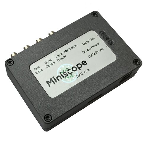
Older Miniscope DAQs are labelled “Aux Input” and “Input Trigger”. These are relabelled in new Miniscope DAQs as “Dig. In 0” and “Dig. In 1” respectively to be consistent with v1.1.4+ versions of the firmware.
The I/O on the Miniscope DAQ operate at a 3.3V logic level and the inputs are 5V tolerant. Miniscope DAQs with the latest firmware from Open Ephys have the following input and output ports:
Digital Inputs: two digital input channels that can be used to log events, gate data acquisition, recording to file, LED on/off state, toggle the excitation light, etc. The functionality is defined by the bonsai workflow.
Sync Output: a digital output channel in which every rising and falling edge indicates a new frame captured by the connected device. This output is recommended for synchronization of multiple hardware with an external acquisition device with a hardware clock.
External Power#
By default, the Miniscope-DAQ is set to use USB power. However, it can be set to use an external power source for particularly power-intensive applications in which USB3.0 cannot provide sufficient power. To use an external power source instead of USB3.0:
Unscrew all four fasteners that fasten the Miniscope-DAQ’s enclosure. It might be necessary to apply gentle pressure on the nuts on the bottom of the DAQ to prevent them from turning when unscrewing the screws.
Set the jumper according to which power source you would like to use, either Jack or USB following to the silk screen:
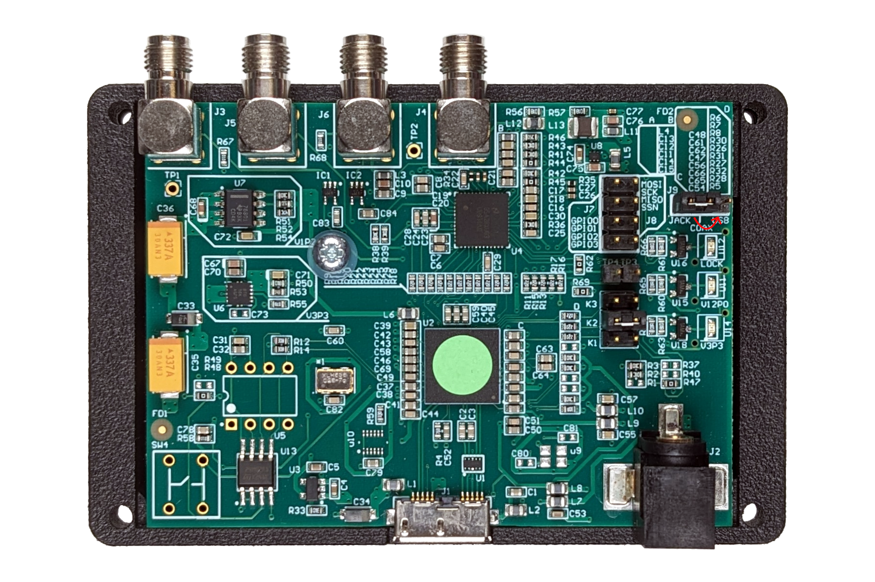
Replace the four fasteners.
Note
If the Miniscope DAQ is set to use external power, the barrel jack must be plugged in to use the device. Conversely, when the Miniscope DAQ is set to USB power, the barrel jack has no effect.
Recommended specifications for an external power supply are as follows:
Output voltage
Warning
Do not exceed 9.0 VDC at the external power jack to the Miniscope DAQ. Exceeding this voltage can damage the device.
To dial in the ideal power supply voltage for your application, you can use an adjustable power supply to power the DAQ and monitor the voltage at the miniscope as described in Measuring Voltage to stay within the operating voltage range of the miniscope and the DAQ. If you don’t have a variable power supply, in most cases a 6V power adapter is sufficient to account for the voltage drop.
Output current
Power adapters up to 1A are used even though the current draw by the devices is less.
Center-positive polarity
Round barrel plug of 2.5 mm ID and 5.5 mm OD
LED Indicators#
Miniscope-DAQs have the following green LED indicators:
DAQ Power: This LED indicates the Miniscope-DAQ is receiving power. Establishing the USB connection between the Miniscope-DAQ and your PC toggles this LED on.
Scope Power: This LED indicates the Miniscope-DAQ is forwarding power to the device that is connected to the Miniscope port.
If the power jumper is set to USB, the LED turns on after establishing the USB connection
If the power jumper is set to Jack, the LED turns on after establishing the USB connection and the external power source connection
Data Link: This LED indicates the Miniscope-DAQ communication is established between the Miniscope-DAQ and the connected device.
Note
If the Miniscope-DAQ is set to use external power, the barrel jack must be plugged in for the Scope Power LED to toggle on.
Syncing Data#
Important
The Sync Output functionality has been corrected in firmware v1.1+ and software v0.4+ to ensure that each time a frame is captured by the Miniscope, the Miniscope DAQ toggles the Sync Output and FrameNumber increments by one. Use the latest Miniscope DAQ firmware and the latest OpenEphys.Miniscope Bonsai package from Open Ephys to ensure hardware synchronization.
Data from the Miniscope is transmitted over USB to the PC. While these frames can be timestamped in software, these software timestamps are only accurate within a few milliseconds of when the frame was actually captured by the Miniscope DAQ, which is insufficient for higher-precision synchronization.
To address this, the Miniscope DAQ provides a Sync Output signal: a digital TTL line that toggles its state within microseconds of capturing each frame. However, frames can drop in transit between the Miniscope DAQ and the computer when the computer is busy, in which case a TTL toggle appears on the Sync Output channel with no corresponding image or quaternion data in the recorded file. The Sync Output alone therefore cannot tell you which sync edge corresponds to which frame when frames are dropped. That is why the v1.1 version of the Miniscope DAQ introduced a FrameNumber member in the UclaMiniscopeV4DataFrame: an integer carried on each frame emitted by the UclaMiniscopeV4 node and incremented by one for every frame captured by the Miniscope DAQ. Now, each Sync Output toggle can easily be matched to specific frames in the Miniscope video stream by counting edges on the Sync Output signal.
For strict data syncing requirements, best practice is to timestamp the Sync Output with external hardware and record FrameNumber alongside the video. You can then determine which rising/falling edge on the Sync Output corresponds to which frame by counting the Sync Output edges in the external hardware data and corroborating them against the frame numbers in the recorded file. The Sync Output starts toggling once Bonsai subscribes to the UclaMiniscopeV4 node, and frame numbers start at 0. Frame dropped on the the way to the PC are reflected by non-consecutive frame numbers or larger inter-frame intervals in software timestamps. For example, Windows often internally skips the first frame received from the Miniscope, so even though you observe a TTL toggle on the Sync Output at the start of the session, you might not receive a frame corresponding to frame 0, in which case FrameNumber in the recorded file will start at 1.
If you are struggling with dropped frames, try changing USB ports, USB drivers, and removing other devices sharing the USB bus. Dropped frames are due to limited USB bandwidth and timing constraints; on a proper setup, expect a dropped frame every few thousand frames.