Automating Tether Commutation#
Use the tabs to follow the tutorial with the Open Ephys Acquisition Board or ONIX
Note
Following this tutorial requires a data acquisition system (Gen 3 Acquisition Board or ONIX), a compatible 3D capable headstage, and an Open Ephys commutator (coax commutator for ONIX and SPI commutator for acquisition board).
Most acquisition systems rely on a tether to transmit power and data between the headstage and the data acquisition controller. As the animal moves around during freely behaving experiments, the tether can get twisted and tangled which risks exerting torque on the animal. This can be is mitigated by using a commutator, a device that untwists the tether as the animal moves around while maintaining electrical continuity between the headstage on the animal and data acquisition controller. Our commutators don’t require tether torque measurements to know in which direction to compensate for the twists. Instead, they use information from absolute orientation sensors on our 3D capable headstages. Torque-free automatic commutation relieves strain from the animal, encouraging more naturalistic behaviors and enabling long-term recordings.
This tutorial demonstrates how to automate commutation using the Open Ephys GUI, a 3D capable headstage, and an Open Ephys commutator.
Hardware Configuration#
Make sure you have a 3D capable SPI headstage which have an Inertial Measurement Unit (IMU).
Follow the Acquisition Board Quick Start Guide to establish the following necessary acquisition board connections:
USB 3.0 connection between the acquisition board and the PC.
+5V connection between the acquisition board and an AC power source.
Follow the SPI Commutator Connections section of the commutator hardware docs to establish the following necessary commutator connections:
SPI connection between the commutator’s stator and the acquisition board.
SPI connection between the commutator’s rotor and the 3D capable headstage.
USB connection between the commutator and the PC.
Make sure you have a 3D capable ONIX headstage which have an Inertial Measurement Unit (IMU), specifically, a BNO055 device.
Follow the ONIX Hardware Guide to establish the following necessary ONIX connections:
2x (A & B) coaxial connections between the breakout board and the PCIe host.
SDR connection between the breakout board and the PCIe host.
Follow the Coax Commutator Connections section of the commutator hardware docs to establish the following necessary commutator connections:
Coaxial connection(s) between the commutator’s stator(s) and the acquisition board.
Coaxial connection(s) between the commutator’s rotor(s) and the 3D capable headstage.
USB connection between the commutator and the PC.
Software Configuration#
In the Open Ephys GUI, download the source processor for your hardware (Acquisition Board or ONIX Source) via “File > Plugin Installer”.
Download the signal chain that corresponds to which hardware you are using.
Open the downloaded signal chain in the GUI.
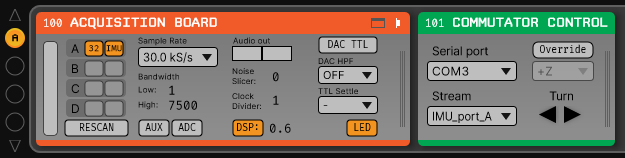
Confirm that “IMU” occupies one of the slots in headstage port indicator in the Acquisition Board processor after the Acquisition Board is initialized and headstage ports are scanned.
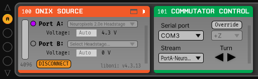
Confirm that one of the data devices on your headstage is a “BNO055” and that it is enabled using the processor’s configuration canvas.
Refer to the Commutator Control page to configure the Commutator Control processor.
The selected Serial port should correspond to the COM port in which the commutator is connected.
The selected Stream should correspond to a 3D data stream. If multiple 3D capable headstages are used, dual commutators, multiple 3D data streams could be available. Select the one you want to use.
For typical usage of an off-the-shelf Open Ephys 3D capable headstage, adjusting the rotation axis is not necessary. If you mount the headstage in a non-conventional location, refer to the IMU Data article and channel maps docs for your particular hardware to figure out how to set the rotation axis.
Make sure the GUI has connected to the acquisition system and click the ▶ play button in the top-right corner. The commutator now follows the rotation of the headstage.