Breakout Board Guide#
Warning
Always make sure the PC is powered off before connecting or disconnecting the Breakout Board. Neglecting to do this will damage the PCIe Controller.
Setup#
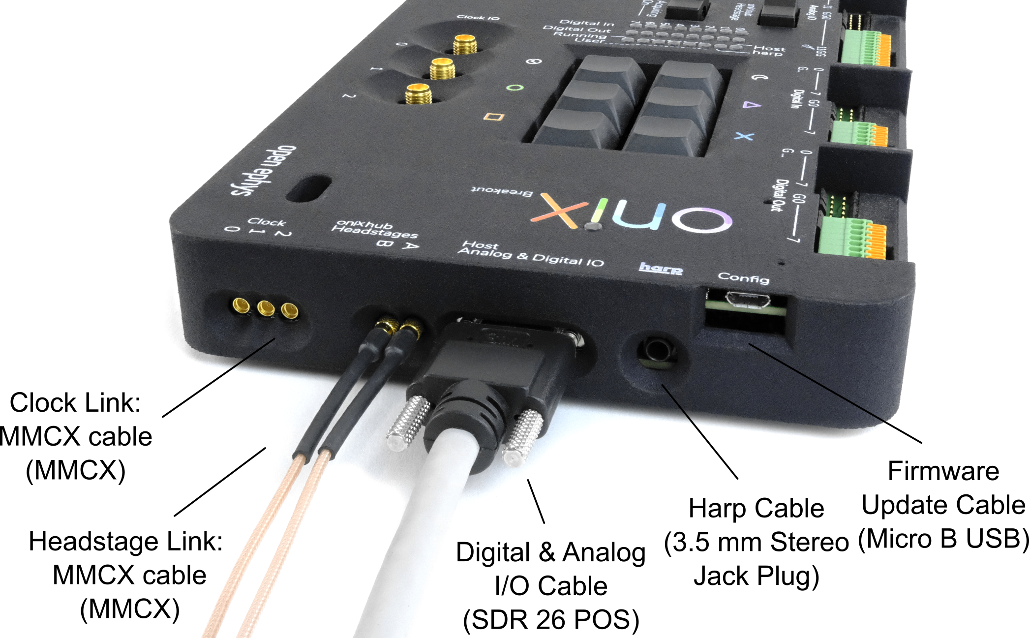
The Breakout Board provides access to signals to and from the PCIe Controller. Each controller is connected to a breakout board using the following connections:
Digital and analog I/O (Required for breakout board operation): A single shrunk delta ribbon (SDR) cable is used for all auxiliary IO and provide power to the Breakout Board.
Headstage links (Required for headstages): A single MMCX coaxial cable is used for each headstage port.
High speed clocks (Optional): A single MMCX coaxial cable is used for each clock signal
Configuration (Optional): Micro USB used to update the breakout gateware.
Refer to the PCIe Controller documentation for a detailed description of how each of these signal lines are acquired.
Note
There may be more headstage ports present on the breakout board than are available on a particular controller. For instance, PCIe Controller has two coaxial links, but the v1.5beta breakout board provides four.
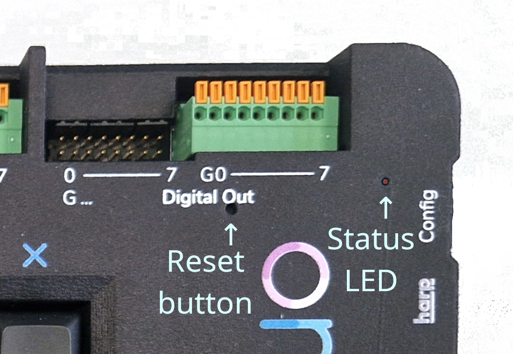
Reset Button#
There are two holes on the breakout board that allow access to the onboard FPGA reset button and status LED. The reset hole is located just below the ‘Digital Out’ marking, and can be used to access the reset button on the onboard FPGA by inserting a thin wire or pin. The onboard FPGA status can be inspected by looking into the status LED hole.
SDR Cable#
Plug in the SDR cable for analog and digital I/O.
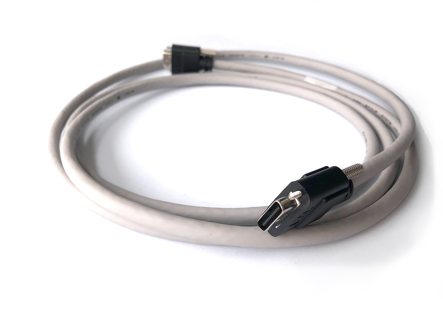
Use the SDR to SDR 26 POS cable to connect the Breakout Board to the PCIe Controller.
Though one end of this cable is marked with ‘camera’, the cable is symmetrical for our purposes, so it can be connected in either direction.
The Breakout Board will power on soon after the host computer is powered.
Attention
Some boards have a bug in the power on sequence that means a reset is required before the board will work. This has been fixed in later revisions. If the RGB LEDs remain off after plugging in the SDR cable, reset the Breakout Board by pressing the onboard FPGA reset button (see above).
MMCX Cables#
Plug in MMCX coaxial connections for headstage ports and clock signals.
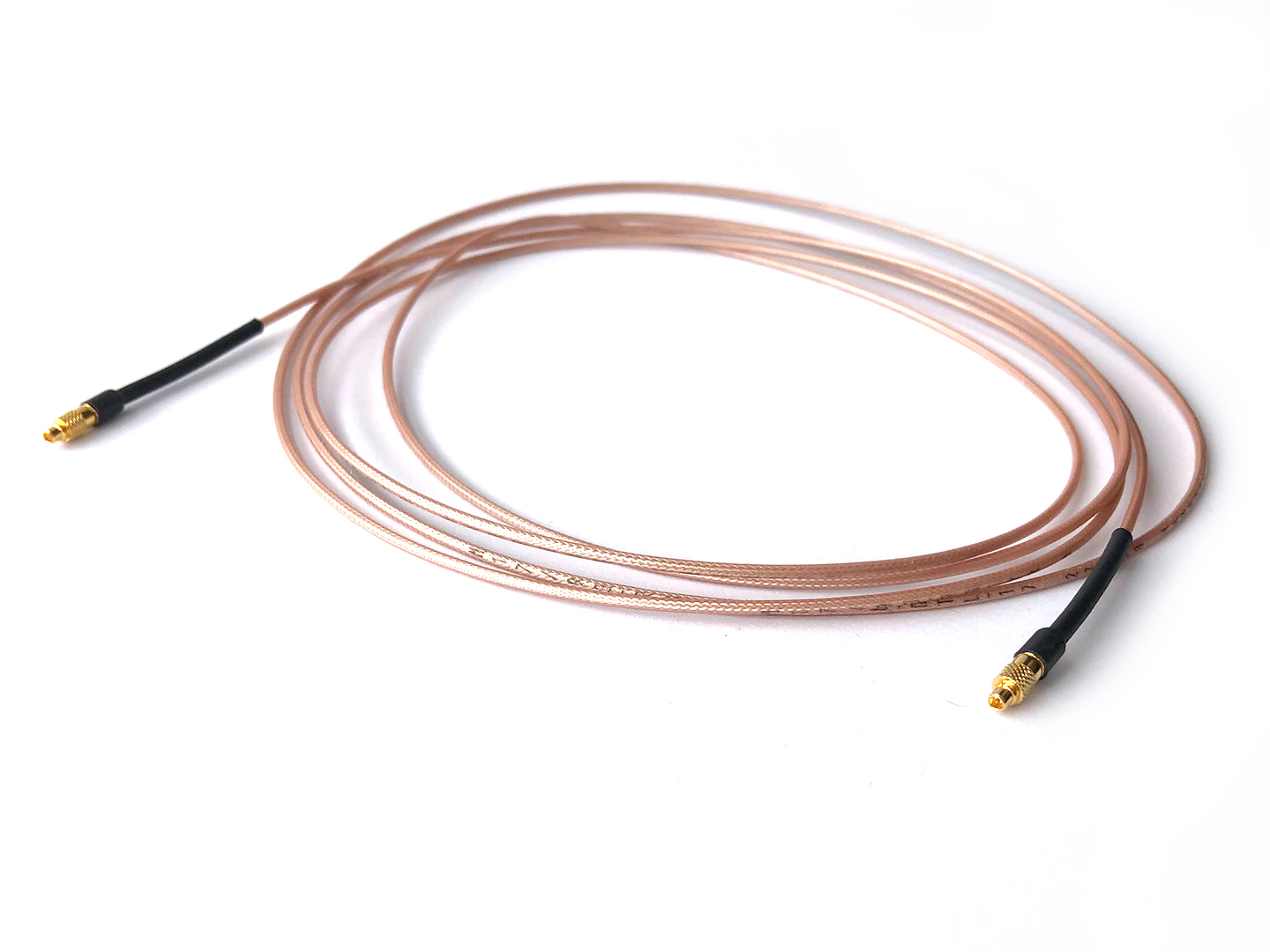
Use the MMCX to MMCX cable to connect a headstage port on the PCIe Controller to the breakout board. A single cable is required for each headstage port.
Make sure that port letter (A, B) on the breakout matches the port letter on the PCIe Controller.
If you are feeding the clock inputs/outputs from the controller through the breakout board, make sure that the port number on the breakout board (0, 1, 2) matches the port number on the PCIe Controller (0 In, 1 In, 2 Out). Clock port 0 is unused so it is not necessary to connect it. Older 3D printed versions of the PCIe bracket label the clock ports as I0, I1, and O - these should connect to the breakout board ports 0, 1, 2, respectively.
Warning
The MMCX connectors can be damaged if they are removed improperly. See this link for information on how to connect and remove MMCX cables without damaging the connector.
LEDs#
RGB LEDs indicate various port states, signal directions, digital signals, and acquisition states, etc. The following diagrams provide definitions for each LED color on the breakout board.
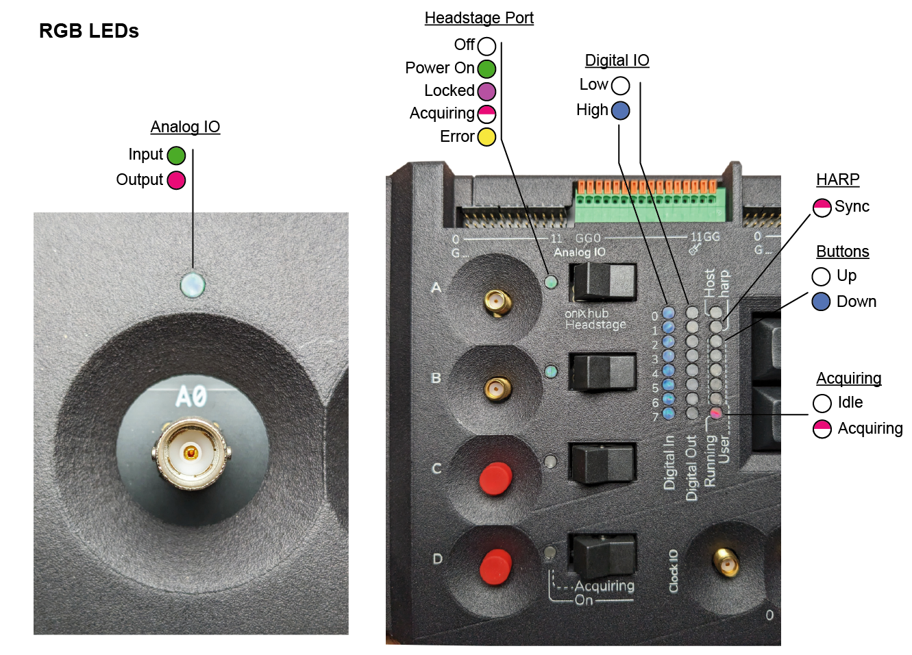
Indication LED legend. Half-filled circles indicate a flashing LED. An error status on a headstage port indicates a loss of lock during acquisition. The headstage connection must be re-established and acquisition restarted.#
Buttons#
Buttons can be used to log various experimental events and turn on and off the indication LEDs. The button state is sent with digital data to the PCIe Controller. Pressing a button sends a single event per change in button state. Holding a button will not result in repeat presses as a keyboard would. Each button sets one bit in a 6-bit word. For exampled
- 000001:
Button 0 pressed (integer value 1)
- 100001:
Button 0 and button 5 pressed (integer value 33)
- 111111:
All buttons pressed (integer value 63)
Additionally, pressing button 0 will toggle indication LED power. This allows all LEDs to be completely turned off for light-sensitive experiments.

Numbers show integer value transmitted to the controller from pressing each. The first button also controls the illumination state of the indication LEDs on the breakout board.#
Gateware#
The breakout board contains a TinyFPGA BX (Lattice ICE40 breakout board) for digital input serialization, digital output deserialization, interpreting user input, and driving indication LEDs. The breakout board gateware is implemented using an open-source toolchain (Yosys and NextPnR).
Follow the instructions in Updating Breakout Board Gateware to update the breakout board gateware to the latest version.