Deprecated since version 1.2.13: Bonsai.ONIX is deprecated.
To use ONIX with Bonsai, refer to the documentation for OpenEphys.Onix1.
RHS2116Device#
A Bonsai source that wraps a RHS2116 device.
- Inputs:
None
- Outputs:
A
RHS2116DataFramethat contains one or more AC ephys and DC high-voltage samples from all 16 ephys channelsThis type is a buffered set of the Device To Host Data Frame specified on the RHS2116 device datasheet.
The number of samples in each output is determined by the
BlockSizeparameter


Configuration#
Configuration is performed using a combination of the property pane and a dedicated configuration GUI.
Property Pane#
Parameters available through the property pane are as follows:
Name |
Type |
Description |
|---|---|---|
EnableStream |
boolean |
Enable the device data stream |
BlockSize |
integer |
The number of 16-channel channel samples that are included in each RHS2116DataFrame. Larger numbers result in less overhead at the cost of larger buffering latencies. |
DataFormat |
enum |
The format of the ephys and DC samples within the RHS2116DataFrame.
|
DSPCutoff |
enum |
Select the low-frequency cutoff for the integrated digital offset removal filter. This filtering is performed following analog to digital conversion. |
AnalogHighCutoff |
enum |
Select a high-frequency cutoff from allowable options. This filtering is performed prior to analog to digital conversion. |
AnalogLowCutoff |
enum |
Select a low-frequency cutoff from allowable options. This filtering is performed prior to analog to digital conversion. |
AnalogLowCutoff |
enum |
Select a low-frequency cutoff from allowable options. This filtering is performed prior to analog to digital conversion during stimulus artifact recovery. It is applied to all channels on the chip following a stimulus pulse on any channel or in response to an external stimulus active signal if RespectExternalActiveStim is set to true. |
SequenceError |
boolean |
Read only register indicating if an ill-defined stimulus sequence was uploaded. |
StimulusSequence |
RHS2116StimulusSequence |
The stimulus sequence definition for this device. Editing this parameter will open the configuration GUI, just like double clicking the node. |
Trigger |
boolean |
Trigger the stimulation sequence. Note: this will only trigger the sequence on this device. To synchronize stimulation across RHS2116 chips, use RHS2116TriggerDevice |
Configuration GUI#
The RHS2116 Configuration GUI, which is a part of the
Bonsai.ONIX.Design package, is opened by double clicking on the
RHS2116Device node when editing the workflow or clicking the ellipsis next to
the StimulusSequence parameter option in the property pane. It is used to
define multichannel stimulus sequences.
The Stimulus Definition tab provides a table of parameters that can be used to define a multichannel stimulus sequence that is delivery using the Trigger register or RHS2116TriggerDevice. After the stimulus is defined, resulting time series waveform can be viewed in the Stimulus Waveform tab. For example, the following figure shows the GUI being used to defines a different pulse pattern on channel 0 and 4 along with the resulting stimulus waveform.
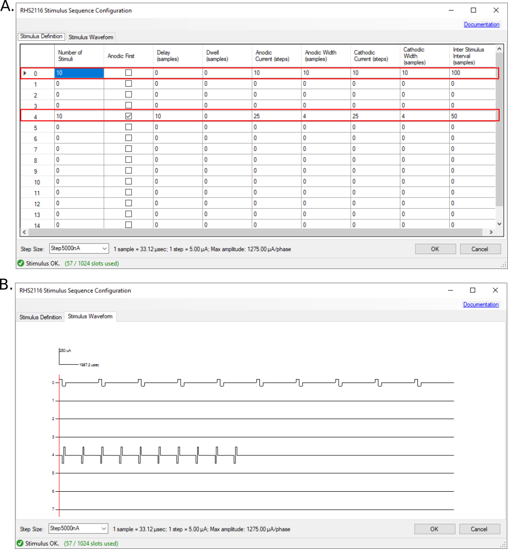
An example multichannel stimulus pulse pattern. A. Stimulus trains are defined for channels 0 and 4 by changing the parameters in the Stimulus Definition table. B. The resulting stimulus waveform can be viewed in the Stimulus Waveform tab.#
Note
You can zoom and pan on the stimulus waveform image.
- Scroll wheel:
Zoom on current mouse position
- Hold scroll & move mouse:
Pan around the image.
The following diagram provides a visual definition for all stimulus parameters that can be provided for a single channel. Each of the chips 16 channels can support an independently configurable stimulus pattern.
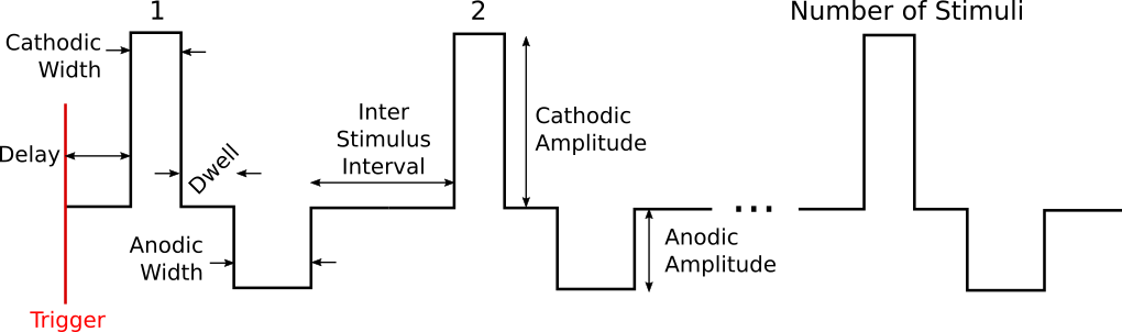
Diagram of stimulus parameters for a single channel#
Note
Stimulus parameters are defined using units that are interpretable by the hardware:
- Amplitudes:
“Steps” where a single step is equal to the currently selected Step Size
- Times:
“Samples” (~1/30193 seconds per sample).
Translations of these units into SI units (microseconds and microamps) is provided by the informational text next to the Step Size selection drop down menu.
Not all stimulus definitions are valid. For instance, zero-area pulses (zero width or amplitude) are not allowed because they don’t make physical sense. Additionally, there is a limited set of on board memory to hold stimulus patterns, and the sequence must fit in this buffer. Stimuli are checked for validity and complexity whenever changes are made to the parameter table and the status of the current stimulus pattern is displayed in the lower left corner of the GUI window. Invalid stimulus patterns (a sequence that is not well defined or too complex) will not be uploaded to the headstage. Additionally, invalid patterns will not be displayed in the waveform viewer.
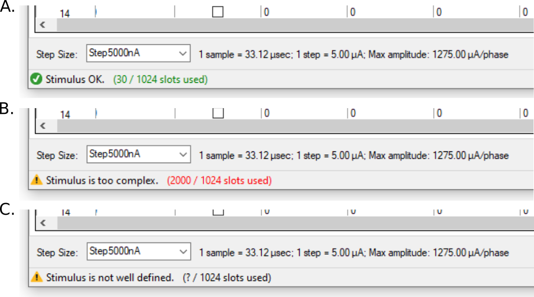
Stimulus patterns must be well defined and fit in on board memory. The status text at the bottom left of the GUI provides information on the validity of the currently defined stimulus pattern and if it will fits in on board memory (green text) or is too complex (red text). A A well defined pattern. B A well defined stimulus that is too complex to fit into headstage memory. C A stimulus pattern is not well defined (e.g. zero area pulses, zero inter stimulus interval for a pulse train with more than 1 stimulus, etc).#
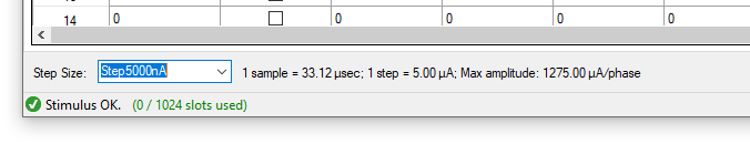
Finally, there is a drop-down menu that allows the user to select stimulus Step Size.
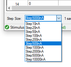
Step Size drop-down menu.#
This selection determines how amplitude “Steps” in the stimulus definition table are mapped into real-world stimulus current. A larger step size allows higher current pulses at the cost of resolution. The value that is chosen should be the minimum value that supports the maximal desired stimulus amplitude. The maximum ache viable current and microamps per step corresponding to a given Step Size selection are displayed in the informational text to the right of the drop down menu.