
Recording Data with the Miniscope GUI#
This page covers the Recording section of the Miniscope GUI’s control panel: where data goes, the three recording modes, and the files each recording produces. For the rest of the interface, see Miniscope GUI Reference.
Choosing Where Data Goes#
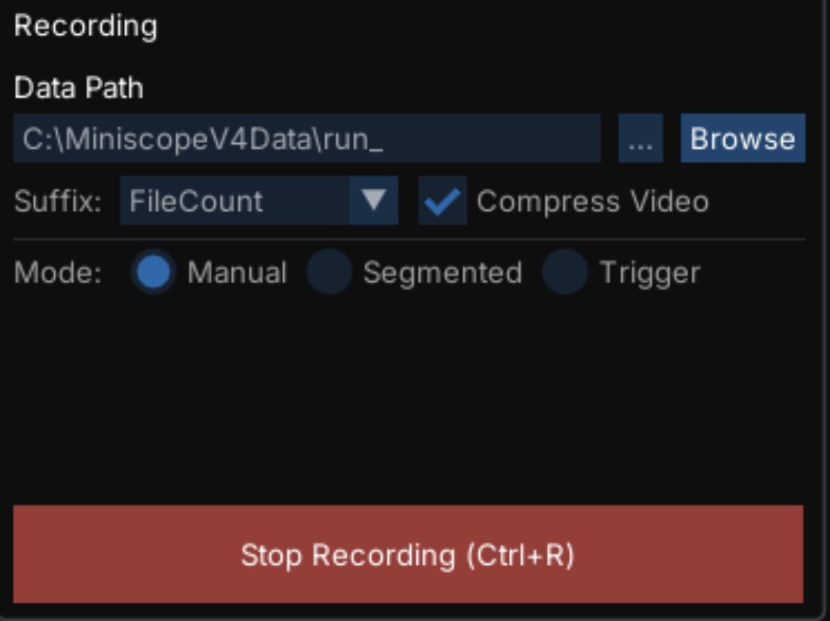
- Data Path:
A folder plus a base file name, which together determine where every file produced during acquisition is written. Click
...to pick them with a file dialog, or type the path directly. Browse opens the folder in File Explorer so you can check previously saved data.- Suffix:
The text inserted between the base name and the extension to keep successive recordings from overwriting one another:
FileCount appends an incrementing number (
run_0,run_1, …). The count is resolved across all file types at once, so a set of files always shares one index.Timestamp appends the recording’s date and time.
- Mode:
Chooses how a recording is started and stopped: Manual, Segmented, or Trigger. Each is described in Recording Modes below.
- Compress Video:
Encodes the video with the
MJPGcompression codec instead of the uncompressedY800codec. This produces substantially smaller files at the cost of higher CPU usage during recording, and, because MJPEG is a lossy codec, some loss of image fidelity.
The data path, suffix, and compression cannot be changed while a recording is running or armed. If you press Record with no data path set, the GUI opens the file dialog first and then starts the recording once you have chosen one.
Important
Recording is only available while acquisition is running. Press Start Acquisition first.
Recording Modes#
Manual#
Recording starts when you press Record and stops when you press Stop Recording (or Ctrl+R for either). One set of files is produced per recording.
Segmented#
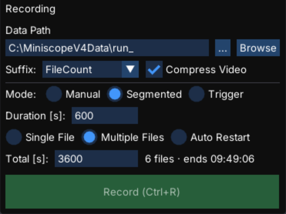
Recording is driven by a timer. Set Duration [s] (the length of each file) and then choose how the segments behave:
- Single File:
Records one file and stops automatically once the duration elapses. Use this for fixed-length trials.
- Multiple Files:
Splits a long recording into successive files of the duration set above, and stops once Total [s] is reached. The GUI shows how many files this will produce and the wall-clock time the recording will end.
Splitting a long session into segments keeps individual video files to a manageable size.
- Auto Restart:
Starts a new file every time the duration elapses, and keeps going until you press Stop Recording. Use this for open-ended sessions where you still want bounded file sizes.
Trigger#
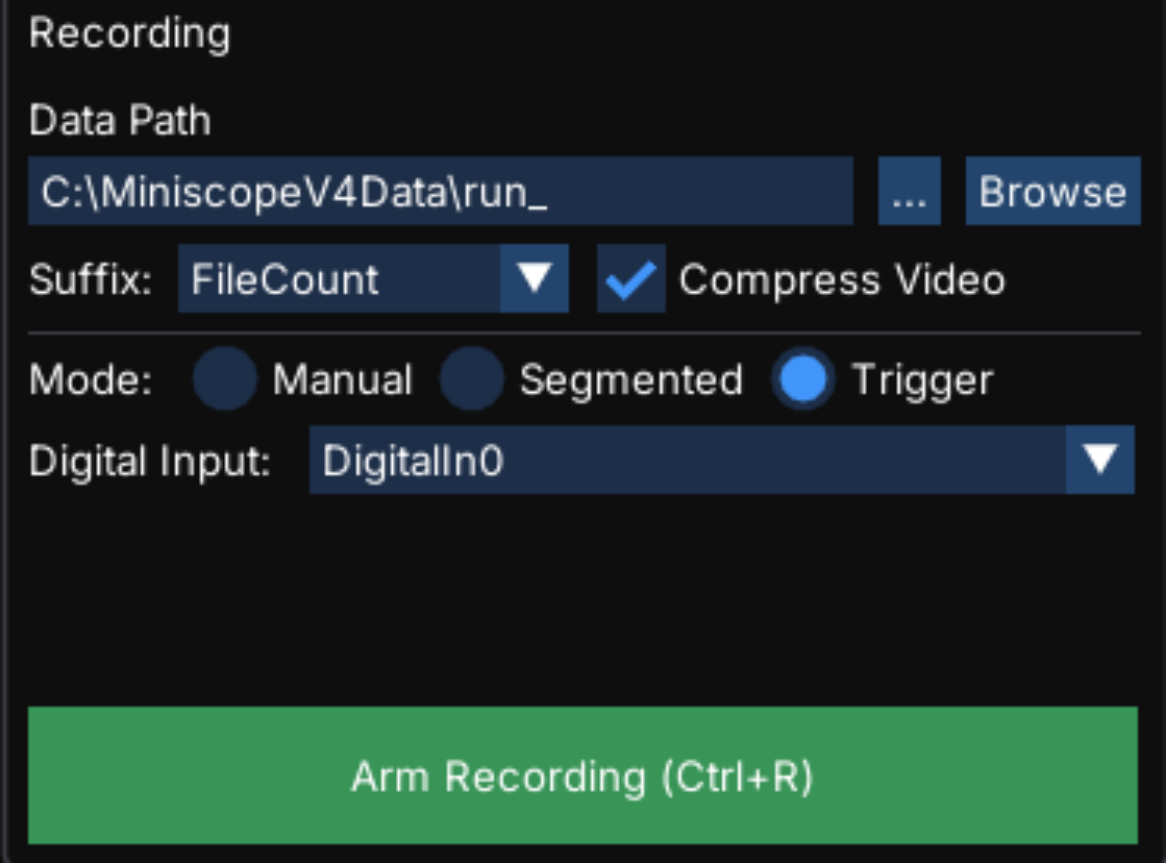
Recording is gated by a hardware digital signal on the Miniscope DAQ. Use this to align imaging with an external system: a behavior rig, a stimulus generator, or another acquisition system.
- Digital Input:
Which input line gates the recording,
DigitalIn0orDigitalIn1.
Press Arm Recording to arm the GUI (the button becomes Disarm). From then on, data is recorded whenever the selected input is high and not recorded when it is low. Each high period produces its own set of files.
Connect the trigger source to the corresponding Dig. In port using an SMA cable, or an adapter such as a BNC-SMA adapter.
Tip
The state of both digital inputs is plotted beneath the orientation traces in the Euler Angles and Quaternion signal tabs. Watch those plots to confirm the trigger is reaching the DAQ before arming.
Note
The LED Trigger setting in the Miniscope section is separate from this mode. It gates the excitation LED on a digital input, and can be pointed at the same input to keep the LED off between triggered recordings. See Miniscope GUI Reference.
The Files a Recording Produces#
Each recording writes four files that share one base name and suffix, so a set is always easy to identify:
Extension |
Contents |
|---|---|
|
The image data, written with the |
|
Per-frame metadata: frame number, hardware time, orientation quaternion, digital input states, and a host timestamp. |
|
Every console message produced while the recording ran, timestamped and tagged with the frame number it occurred on. |
|
A snapshot of the complete GUI configuration at the moment recording started. |
Recording a configuration snapshot alongside every recording means the exact acquisition settings for any dataset can always be recovered, and reloaded, later.
Per-Frame Metadata#
The .csv file has one row per recorded frame:
FrameNumber,HardwareTime,Quaternion_X,Quaternion_Y,Quaternion_Z,Quaternion_W,DigitalIn0,DigitalIn1,Timestamp
118,3861,0.0215548109,0.0887330621,0.141699627,0.851352096,False,False,2026-07-30T14:59:24.0823808-04:00
119,3894,0.280063719,0.165637791,0.218259633,0.642150462,False,False,2026-07-30T14:59:24.1033472-04:00
- FrameNumber:
The frame counter reported by the Miniscope. Gaps in this column indicate dropped frames.
- HardwareTime:
The Miniscope’s own hardware clock, in milliseconds.
- Quaternion_*:
The orientation reported by the on-board IMU for that frame.
- DigitalIn0/1:
The state of the DAQ’s digital inputs at that frame.
- Timestamp:
The host computer’s clock when the frame was received, which is what you use to align the recording with other systems on the same machine.
Recording Log#
The .log file is a CSV of the console messages recorded during the session:
Timestamp,FrameNumber,Level,Message
2026-07-30 14:59:23.921,118,Info,Recording started
2026-07-30 14:59:27.124,216,Info,Stopping recording.
2026-07-30 14:59:27.126,216,Info,Recording stopped
Because hardware setting changes are logged as they happen, a mid-recording change to LED brightness or focus appears here with the frame number it took effect on.
Captured Images#
Images saved with Capture Current Image (C) are written next to the recording data as PNG
files named <base name>frame_<frame number>_<yyyyMMdd_HHmmss_fff>.png. These are not tied to a
recording; they can be captured any time acquisition is running and a data path is set. These images
are what you load later as a reference image to realign a field of view.
Configuration Files#
The GUI’s entire state is expressible as a single YAML file: the selected camera, the Miniscope and commutator settings, the display settings for every image tab, and the file settings.
These files are used in three ways:
Automatically, between sessions. The GUI saves its state to
default_miniscopev4_config.ymlin its install folder and reloads it on the next launch, so the GUI comes back exactly as you left it. If that file is missing or unreadable, the GUI warns in the console and falls back to defaults.Automatically, with each recording. A snapshot is written alongside every recording, as described above.
Manually, with Export and Import. The buttons at the top of the control panel write and read a configuration anywhere on disk. Export a configuration once a protocol is dialed in, then import it if a setting is changed accidentally, or share it with a colleague to reproduce the same acquisition settings on another rig.
Tip
To resume from a previous recording’s exact settings, import that recording’s .yml
file.