Optomechanical Design#
Optomechanical Overview#
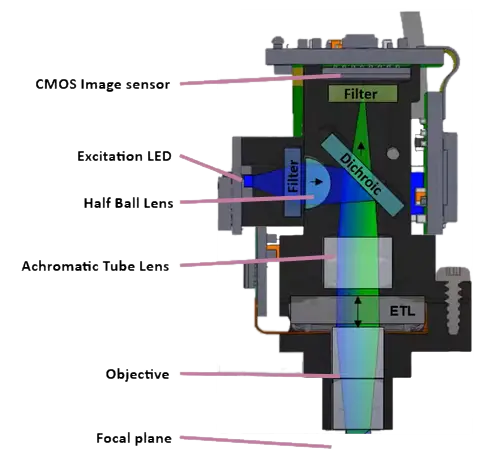
The UCLA Miniscope v4 is a miniaturized epifluorescent/widefield microscope. An LED serves as the excitation light source. The excitation filter filters the excitation light to prevent undesired wavelengths from entering the miniscope. Excitation light is reflected by the dichroic mirror and refracted by a series of lenses such that it illuminates the imaging target sufficiently uniformly. Fluoresced (emission) light is collected by the miniscope’s objective, refracted by the tube lense, and transmitted through the dichroic mirror to form an image of the specimen’s fluoresced light on the miniscope’s sensor. The electro-tunable lens ETL (sometimes also referred to as electrowetting lens, EWL) is a lens formed by fluid in a membrane that changes shape according to the average voltage applied across the membrane, providing dynamic imaging depth adjustment.
For a more comprehensive description of the UCLA Miniscope v4’s constituent parts and optomechanical design, visit the Parts List from the UCLA Miniscope v4 GitHub wiki.
For more information, please refer to the relevant parts of the 2021 Miniscope Workshop video Imaging principles & Miniscope design.
The UCLA Miniscope v4 mechanics can be thought of as comprised from four modules.
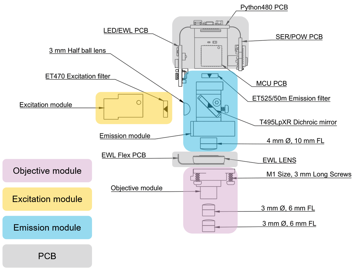
UCLA Miniscopes v4 Optomechanical Modules
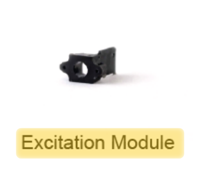
Mounts the excitation filter against the excitation light source which blocks wavelengths of light that could pollute the UCLA Miniscope v4’s sensor with undesirable light
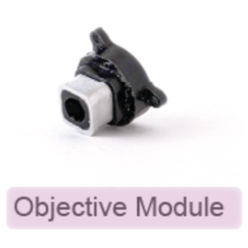
Mounts a combination of off-the-shelf achromatic lenses which can be swapped out to adjust the field-of-view/magnification, working distance, spatial resolution, and effective NA of the microscope. The roles of this module is to:
Help illuminate the sample with excitation light from the excitation light source
Collect emmision light from the sample and roughly collimate it into the excitation module
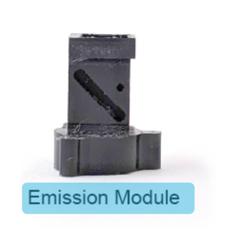
Mounts the emission filter against the sensor which blocks wavelengths of light that could pollute the UCLA Miniscope v4’s sensor with undesirable light
Mounts the dichroic mirror which reflects excitation light into the objective module and transmits emission light into the imaging sensor
Mounts 3mm half ball lens which improves the illumination profile at the imaging sample
Mounts 4mm diameter, 10mm focal length lens to operate as a tube lens
Mounts and electrically connects the various electronics for controlling the sensor, ETL, LED and communication with the data acquisition hardware
Design and Production Files#
All the design and production files for the UCLA Miniscope v4 PCB are available for download in the UCLA Miniscope v4’s official GitHub repository: Aharoni-Lab/Miniscope-v4. For quick-and-easy access, direct links to optomechanical design and production files are below.
Some operating systems come with free software that can be used to visualize STEP or STL files. There are also online viewers for these kinds of files. Common MCAD software for editing these kinds of files include Solidworks and Autodesk.
The UCLA Miniscope v4 body parts can be produced in-house with a Formlabs SLA printer or outsourced to a 3D printing services. In either case, ensure the miniscope is printed with black, non-fluorescent resin. The baseplate parts are milled from aluminum.
For more information about procuring parts for building your own miniscope, visit the Parts Procurement page from the UCLA Miniscope v4 GitHub wiki.