HS64 Optical Stimulator#
- Authors:
Jie (Jack) Zhang & Jonathan P. Newman
- Version:
1
- IO:
Register Access
- ONIX ID:
5
- ONIX Hubs:
Description#
The HS64 Optical Stimulator is a two-channel high-current LED/laser diode driver for optogenetic stimulation (On Semi CAT4016). The maximal current can be set over a wide (~10 mA to 800 mA) range via an external digital potentiometer. The optical power can then be adjusted linearly and synchronously across both channels within this range over 8-levels per diode load. This sub-circuit is controlled as a single device using parameters similar to a Master8 or PulsePal.
Register Programming#
Address |
Name |
Access |
Time of Effect |
POR Value |
Reset Action |
Description |
|---|---|---|---|---|---|---|
0x00 |
NULLPARM |
R |
N/A |
0 |
None |
No effect. |
0x01 |
MAXCURRENT |
R/W |
Immediate |
200 |
None |
Max LED/LD current, (0 to 255 = 800mA to 0 mA. See fig 10 of CAT4016 datasheet) |
0x02 |
PULSEMASK |
R/W |
Immediate |
(others => ‘1’) |
None |
Bitmask determining which of the (up to 32) channels is affected by trigger |
0x03 |
PULSEDUR |
R/W |
Immediate |
1000 |
None |
Pulse duration, microseconds |
0x04 |
PULSEPERIOD |
R/W |
Immediate |
50000 |
None |
Inter-pulse interval, microseconds |
0x05 |
BURSTCNT |
R/W |
Immediate |
5 |
None |
Burst duration, number of pulses in burst |
0x06 |
IBI |
R/W |
Immediate |
1000000 |
None |
Inter-burst interval, microseconds |
0x07 |
TRAINCNT |
R/W |
Immediate |
1 |
None |
Pulse train duration, number of bursts in train, 0 = continuous |
0x08 |
TRAINDELAY |
R/W |
Immediate |
0 |
None |
Pulse train delay, microseconds |
0x09 |
TRIGGER |
R/W |
Immediate |
0 |
Default |
Trigger stimulation (1 = deliver) |
0x0a |
ENABLE |
R/W |
Immediate |
0 |
Default |
1: enables the stimulator, 0: stimulator ignores triggers (so that a common trigger can be used) |
0x0b |
RESTMASK |
R/W |
Immediate |
(others => ‘0’) |
None |
Bitmask determining the “off” state of the up to 32 channels |
0x0c |
RESET |
R/W |
Immediate |
0 |
None |
If 1, Reset all parameters to default |
0x0d |
MINRHEOR |
R |
Immediate |
MINRHEOR |
Default |
The series resistor between the potentiometer (rheostat) and RSET bin on the CAT4016 |
0x0e |
POTRES |
R |
Immediate |
POTRES |
Default |
The resistance value of the potentiometer connected in rheostat config to RSET on CAT4016 |
A graphical register definitions are provided in the following diagrams:
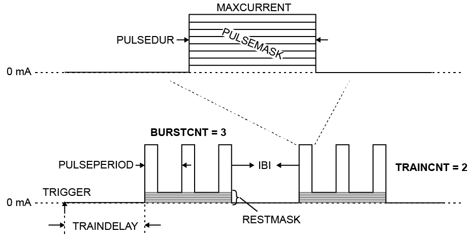
A diagram of the stimulus parameters presented in the HS64 Optical Stimulator Registers table.#
Device To Host Data Frames#
No frames are transmitted to the host.
Host To Device Data Frames#
This device does not accept input frames. All write attempts will fail with an error.