HS64 Electrical Stimulator#
- Authors:
Jie (Jack) Zhang & Jonathan P. Newman
- Version:
1
- IO:
Register Access
- ONIX ID:
4
- ONIX Hubs:
Description#
The HS64 Electrical Stimulator is a combined precision bipolar current source and sequencer for generating electrical stimuli. The circuit consists of an enhanced Howland current pump driven by a DAC. A bipolar 15 volt supply is provided switching regulator. This regulator is only enabled during stimulation epochs in order to minimize switching noise on analog traces. A dual-channel bipolar analog switch sits between the stimulator output and stimulation electrode. Outside of stimulus pulses, it shorts the stimulation electrode to ground to prevent electrolysis due to charge imbalance and sends the stimulator output through a shunt resistor to prevent accumulation of large output voltage due to slight offsets and component mismatch.
Component values have been chosen to optimize circuit stability over a wide range of electrode impedances. Operation remains stable for macroelectrodes (e.g. low-impedance cut stainless-steel wire and microelectrodes up to 1 MOhm at 1kHz). The circuit can produce up to 2.5 mA of bipolar current within the bounds of its ±15V compliance voltage range. Although this circuit consists of multiple components, the firmware permits operation, via register programming, that is very similar to a Master8 or PulsePal.
Warning
This device contains power generation circuitry that operates correctly within a relatively narrow range of input voltages. Make sure your headstage voltage is within spec or this device may produce incorrect stimulus amplitudes.
Register Programming#
Register IO is detailed in the table below.
Address |
Name |
Access |
Time of Effect |
POR Value |
Reset Action |
Description |
|---|---|---|---|---|---|---|
0x00 |
NULLPARM |
R |
N/A |
0 |
None |
No command |
0x01 |
BIPHASIC |
R/W |
Immediate |
1 |
None |
Biphasic pulse (0 = monophasic, 1 = biphasic) |
0x02 |
CURRENT1 |
R/W |
Immediate |
2^(DACREZ - 1) |
None |
Phase 1 current. See (1). |
0x03 |
CURRENT2 |
R/W |
Immediate |
0 |
None |
Phase 2 current. See (1). |
0x04 |
PULSEDUR1 |
R/W |
Immediate |
100 |
None |
Phase 1 duration, microseconds |
0x05 |
INTERPHASEINTERVAL |
R/W |
Immediate |
0 |
None |
Inter-phase interval, microseconds |
0x06 |
PULSEDUR2 |
R/W |
Immediate |
100 |
None |
Phase 2 duration, microseconds |
0x07 |
INTERPULSEINTERVAL |
R/W |
Immediate |
10000 |
None |
Inter-pulse interval, microseconds |
0x08 |
BURSTCNT |
R/W |
Immediate |
10 |
None |
Burst counts, number of pulses |
0x09 |
INTERBURSTINTERVAL |
R/W |
Immediate |
0 |
None |
Inter-burst interval, microseconds |
0x0a |
TRAINCNT |
R/W |
Immediate |
1 |
None |
Pulse train counts, number of bursts |
0x0b |
TRAINDELAY |
R/W |
Immediate |
0 |
None |
Pulse train delay, microseconds |
0x0c |
TRIGGER |
R/W |
Immediate |
0 |
0 |
Trigger stimulation (0 = off, else = deliver continuously) |
0x0d |
POWERON |
R/W |
Immediate |
0 |
None |
Toggle estim power to reduce noise when not in use (0 = off, 1 = on) |
0x0e |
ENABLE |
R/W |
Immediate |
0 |
0 |
1: enables the stimulator, 0: stimulator ignores triggers (so that a common trigger can be used) |
0x0f |
RESTCURRENT |
R/W |
Immediate |
2^(DACREZ - 1) |
None |
Resting current between pulse phases. See (1). |
0x10 |
MASTERRESET |
R/W |
Immediate |
0 |
None |
Reset all parameters to default |
0x11 |
DACREZ |
R |
N/A |
N/A |
None |
Internal DAC resolution in bits, which is a hard-coded circuit parameter. |
A graphical register definitions are provided in the following diagrams:
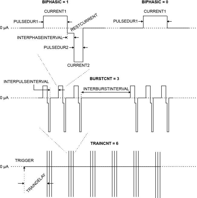
A diagram of the stimulus parameters presented in the HS64 Electrical Stimulator Registers table.#
For registers specifying electrical current, the following transform applies:
where N specifies the bit resolution of the circuit’s DAC, which is made available in the DACREZ register.
Device To Host Data Frames#
No frames are transmitted to the host.
Host To Device Data Frames#
This device does not accept input frames. All write attempts will fail with an error.