Updating Breakout Board Gateware in Windows#
Warning
Connecting or disconnecting the breakout board while the PC is on damages the Controller.
Power off the PC to which the breakout board is connected.
Disconnect the breakout board from the PC by disconnecting the digital and analog I/O grey SDR cable.
Connect a USB-microUSB from the PC you will use to perform the gateware update to the Config port on the side of the breakout board.
Verify the Breakout Board version by looking at the specifications on the product.
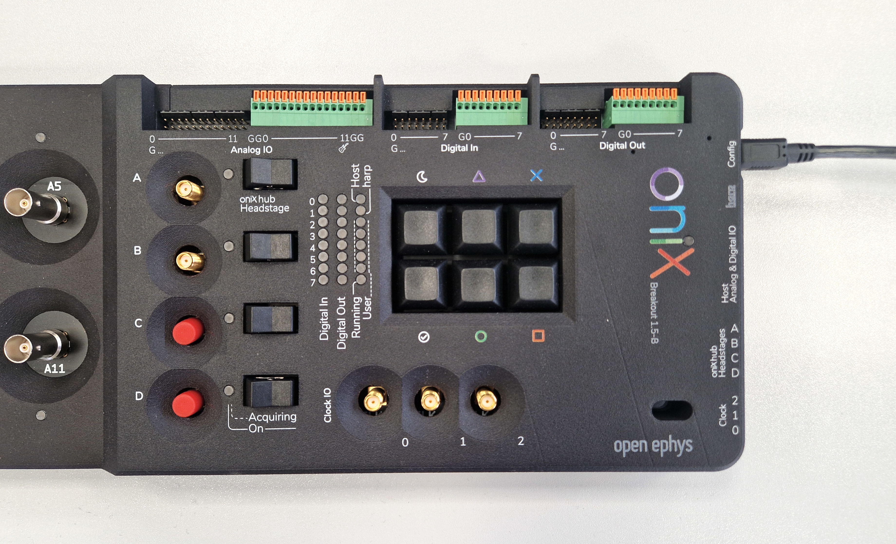
Breakout Board version 1.5 has four headstage ports (only two are enabled).#
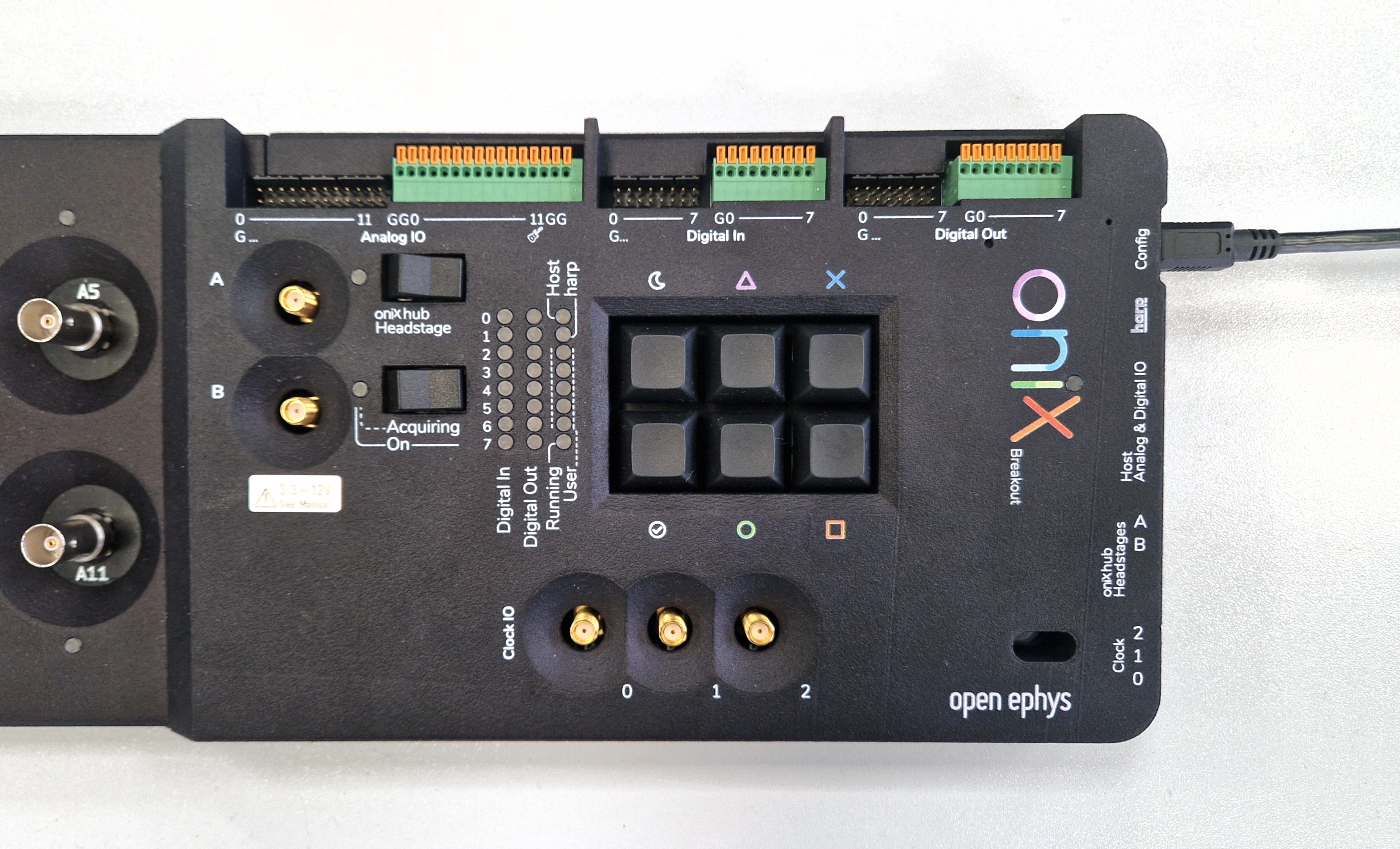
Breakout Board version 1.6 has two headstage ports.#
Download the latest gateware image for your hardware version.
Warning
Make sure that the Breakout Board gateware image you download matches the Breakout Board hardware version you verified in the previous step. An incorrect gateware version will not report any error while updating but will cause failures during operation.
Download the Breakout Board Upload Tool utilities package and unzip it. Navigate to this folder using a console. Place the gateware image you downloaded in the previous step in the same folder.
Press the onboard FPGA reset button (using a thin tool that fits the reset hole) to put the device into bootloader mode. The onboard FPGA status LED will breathe to indicate it is ready to be programmed.
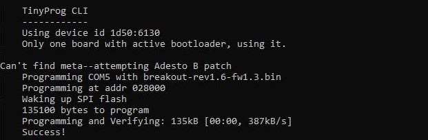
From the console, use the following command with the correct name of the gateware image you downloaded to program the device:
$ tinyprog.exe -p breakout_gateware_image_filename.bit
Check that the breakout board gateware was programmed successfully
Disconnect the USB-microUSB cable from the breakout board
Power off the PC to which the breakout board will be connected.
Connect the breakout board to the PC using the digital and analog I/O grey SDR cable, and any necessary headstage links as per the setup guide.