Neuropixels PXI#
Plugin Type |
Source |
Platforms |
Windows only |
Built in? |
No |
Key Developers |
Josh Siegle, Pavel Kulik |
Source Code |
Installing and upgrading#
The Neuropixels PXI plugin is not included by default in the Open Ephys GUI. To install, use ctrl-P or ⌘P to open the Plugin Installer, browse to the “Neuropixels PXI” plugin, and click the “Install” button. This will also install the OneBox plugin. Alternatively, you can select the “Neuropixels” default configuration the first time the GUI is launched, and the plugin will be downloaded and installed automatically.
The Plugin Installer also allows you to upgrade to the latest version of this plugin, if it’s already installed.
Hardware requirements#
One computer (see Computer requirements for recommended specs)
One PXI chassis (e.g. NI PXIe-1071, PXIe-1082, PXIe-1083, or ADLINK PXES-2301)
(optional) One PXI-based analog and digital I/O module (see the NI-DAQmx page for a list of hardware we’ve tested)
For chassis without a built-in controller (e.g. NI PXIe-1071, NI PXIe-1082, or ADLINK PXES-2301), you’ll need:
One PXI remote control module (we’ve tested NI PXIe-8381 and PXIe-8398) – requires NIDAQmx driver
One PCIe interface card (we’ve tested National Instruments PCIe-8381, PCIe-8382, and PCIe-8398)
MXI-Express Cables to connect the remote control module to the PCIe card
For chassis with a built-in Thunderbolt controller (e.g. PXIe-1083):
One Thunderbolt interface card that’s compatible with your motherboard
One sufficiently long Thunderbolt cable
Ordered via neuropixels.org:
One or more Neuropixels basestations (can acquire data from 4 Neuropixels 1.0 probes per basestation)
One or more Neuropixels cables (black + yellow twisted pair, USB-C to Omnetics)
One or more Neuropixels headstages
One or more Neuropixels probes
Compatible probes#
This plugin can stream data from the following Neuropixels probe types:
Probe |
Channels |
Plugin Version |
Min. PXI Firmware |
Neuropixels 1.0 |
384 AP, 384 LFP |
||
Neuropixels NHP Prototype (10 mm, 25 mm, and 45 mm) |
384 AP, 384 LFP |
≥0.2.x |
|
Neuropixels NHP 128 CH Passive |
128 AP, 128 LFP |
≥0.2.x |
BS137, BSC176 |
Neuropixels NHP Commercial (10 mm) |
384 AP, 384 LFP |
≥0.5.x |
BS169, BSC176 |
Neuropixels UHD Phase 1 |
384 AP, 384 LFP |
||
Neuropixels UHD Phase 2 (switchable) |
384 AP, 384 LFP |
≥0.2.x |
BS137, BSC176 |
Neuropixels UHD Phase 3 (ultradense) |
384 AP, 384 LFP |
≥0.5.x |
BS169, BSC176 |
Neuropixels 2.0 (beta) |
384 wideband |
≥0.2.x |
BS137, BSC176 |
Neuropixels 2.0 (multishank) |
384 wideband |
≥0.6.x |
BS169, BSC189 |
Neuropixels 2.0 (single shank) |
384 wideband |
≥0.7.x |
BS169, BSC191 |
Neuropixels 2.0 (quad base) |
1536 wideband |
≥2.x.x |
BS226, BSC233 |
Neuropixels Opto |
384 AP, 384 LFP |
≥0.4.x |
Special basestation required |
Connecting to the PXI system#
Installing the drivers#
Before using this plugin, make sure you’ve followed all of the hardware setup steps in the Neuropixels User Manual. Prior to using a Neuropixels PXI basestation on Windows, download and install the Enclustra drivers for each PXIe acquisition module individually as described below.
Mount the PXIe acquisition module(s) in the chassis.
Log in with an account that has administrative privileges and open Device Manager.
- If Enclustra drivers are already installed, uninstall them before upgrading:
Right-click each Enclustra PCI Express Adapter entry.
Select Uninstall device.
If Windows offers a checkbox to delete the driver software, enable it.
Repeat this process for every Enclustra entry in the system, one per Imec basestation card.
Confirm that each device now appears under Other devices as PCI Memory Controller. If it does not, select Action > Scan for hardware changes in Device Manager.
- Install the driver only for entries listed as PCI Memory Controller:
Right-click PCI Memory Controller under Other devices and select Update driver.
Choose Browse my computer for driver software.
Browse to the folder containing the extracted Enclustra driver files and click Next.
Wait for Windows to report that the driver update completed successfully, then close the dialog.
Repeat these steps for each PXIe acquisition module in the chassis.
Reboot the PC and log back in.
Re-open Device Manager and verify that the hardware now appears under Enclustra Devices as Enclustra PCI Express Adapter.
If the device still appears as PCI Memory Controller after rebooting, repeat the installation and confirm that Windows is pointed at the extracted Enclustra driver folder rather than the zip archive itself.
Important
A new version of the Enclustra driver (v1.17) is now available. We strongly recommend that all existing and new users update to this version (linked above) by following the procedure described above. Doing so will help ensure compatibility and reduce the risk of potential issues, including Blue Screen of Death (BSOD) errors during normal operation.
Initializing the plugin#
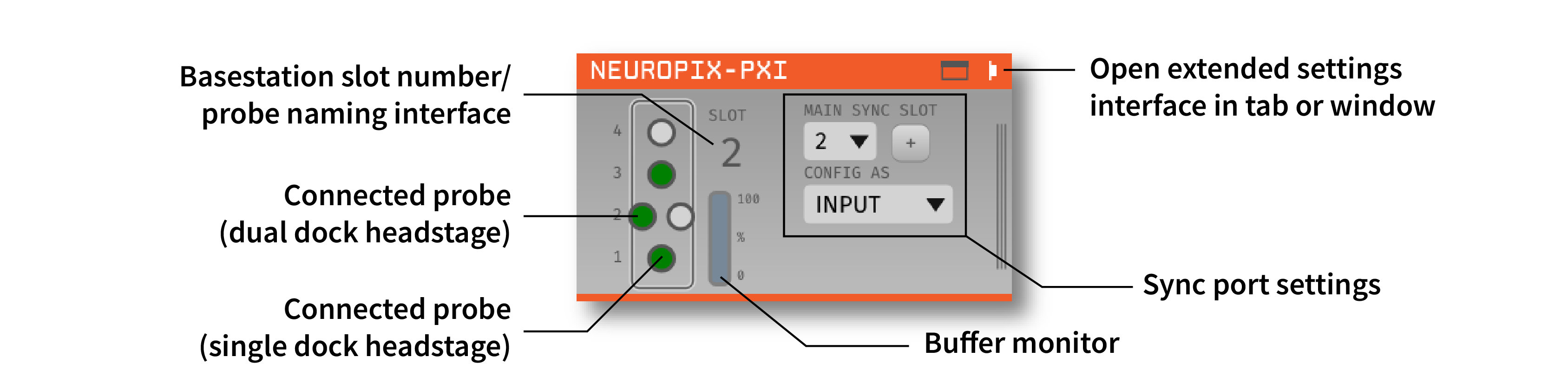
Once your PXI system is up and running, you can drag and drop the “Neuropix-PXI” plugin from the Processor List onto the Editor Viewport. The GUI will automatically connect to any available basestations in your PXI chassis with probes connected. If no basestations are found, the plugin can be run in simulation mode. If no probes are found, the plugin editor will display information about each basestation, and can be used to perform a firmware update (see Updating basestation firmware below).
The editor will automatically create a probe selection interface for each basestation that’s available. Each basestation can communicate with up to 4 probes (for Neuropixels 1.0, NHP, Ultra, and 2.0 quad base) or 8 probes (for 2.0 single and multi shank). When the probes are initially detected, they show up as orange circles. Once they are initialized, connected probes become green. After the probes turn green, the plugin is ready to begin data acquisition.
Troubleshooting connections#
If no basestations are detected, the plugin will display the “No basestations found” message and ask to run in simulation mode. As of plugin version 0.6.0, if a basestation is found but no probes are detected, you will be able to update basestation firmware but not start data acquisition. If a probe is attached but the plugin is still appearing grayed out, the most likely explanation is that the probe is not properly seated in the headstage ZIF connector.
Note
If a basestation is available but no probes are detected, the GUI may print a message about a “firmware version mismatch” to the console. This is an automatic output of the Neuropixels API and can be ignored. Once probes are successfully detected, it should disappear.
Calibrating probes#
Neuropixels probes require calibration in order to function properly. These files can be obtained from IMEC for every probe that you’ve purchased. There should be two files for each 1.0 probe:
<probe_serial_number>_ADCCalibration.csv<probe_serial_number>_gainCalValues.csv
and one file for each 2.0 probe:
<probe_serial_number>_gainCalValues.csv
Any probes detected by the Neuropixels PXI plugin will be calibrated automatically when the plugin is loaded, provided that calibration files are stored in one of the following locations:
For GUI versions prior to v1.0.0:
C:\ProgramData\Open Ephys\CalibrationInfo\<probe_serial_number>(recommended - note that ProgramData may be a hidden folder on your system, so you’ll need to change the File Explorer options to show hidden files)
For GUI versions 1.0.0 and later:
C:\Users\<username>\AppData\Local\Open Ephys\CalibrationInfo\<probe_serial_number>(recommended - note that AppData may be a hidden folder on your system, so you’ll need to change the File Explorer options to show hidden files)
For any version of the GUI:
<open-ephys-executable-folder>\CalibrationInfo\<probe_serial_number>(if you used the Open Ephys installer, the executable will be located inC:\Program Files\Open Ephys)
If these files cannot be found, a warning message will appear. It’s still possible to acquire data from uncalibrated probes, but this data should be used for testing purposes only. The calibration files must copied to the correct location prior to running any actual experiments.
Configuring probe settings#
To open the probe settings interface, press the “window” or “tab” button in the upper-right corner of the editor:

Each probe has its own interface for updating settings, which is customized for each probe type. Selecting the green button corresponding to the probe’s basestation and port in the plugin editor allows you to access the parameters for a particular probe. The button that is highlighted in light green indicates the probe whose settings are currently being viewed.
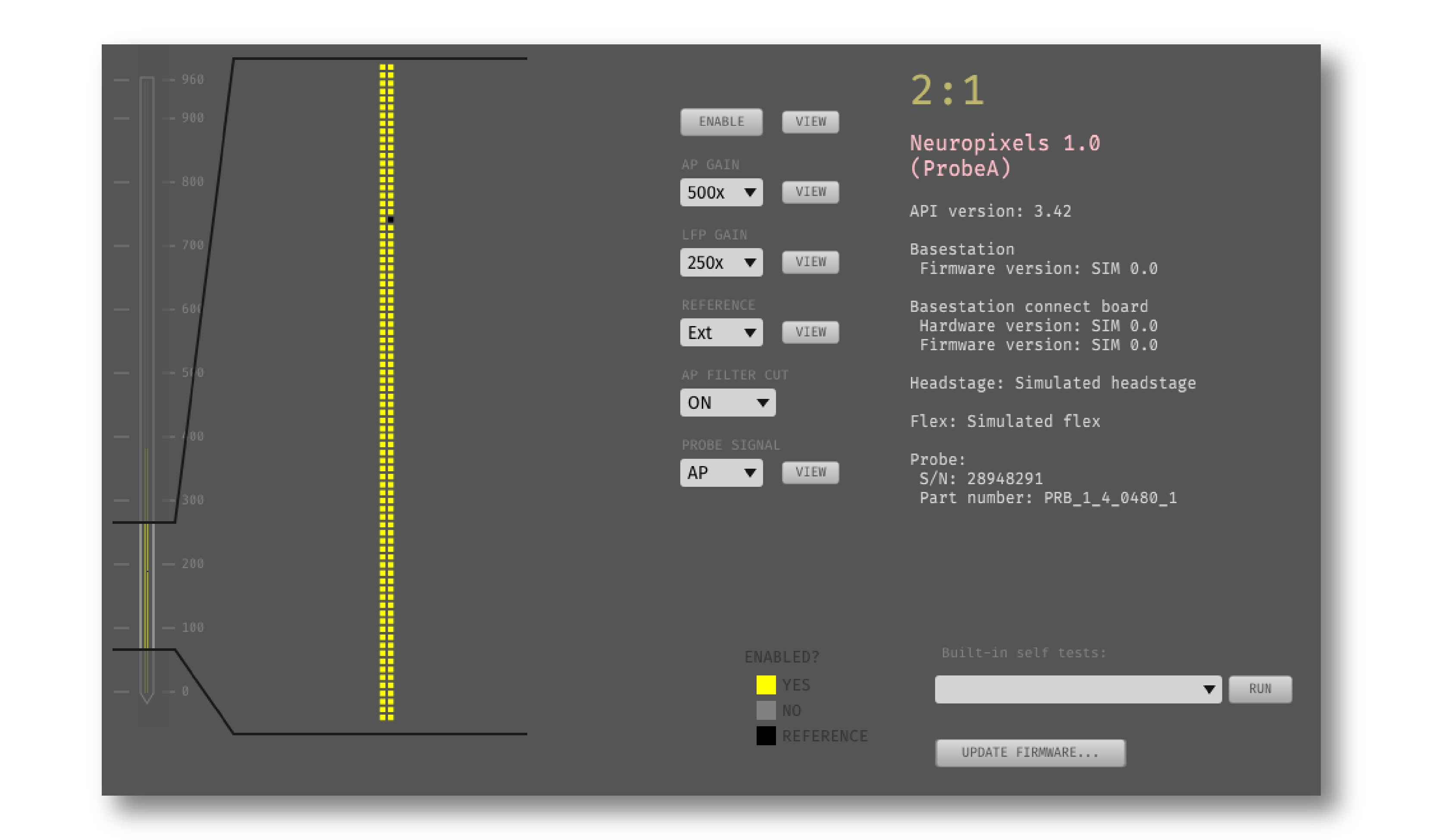
Here is an example of the settings interface for a Neuropixels 1.0 probe:
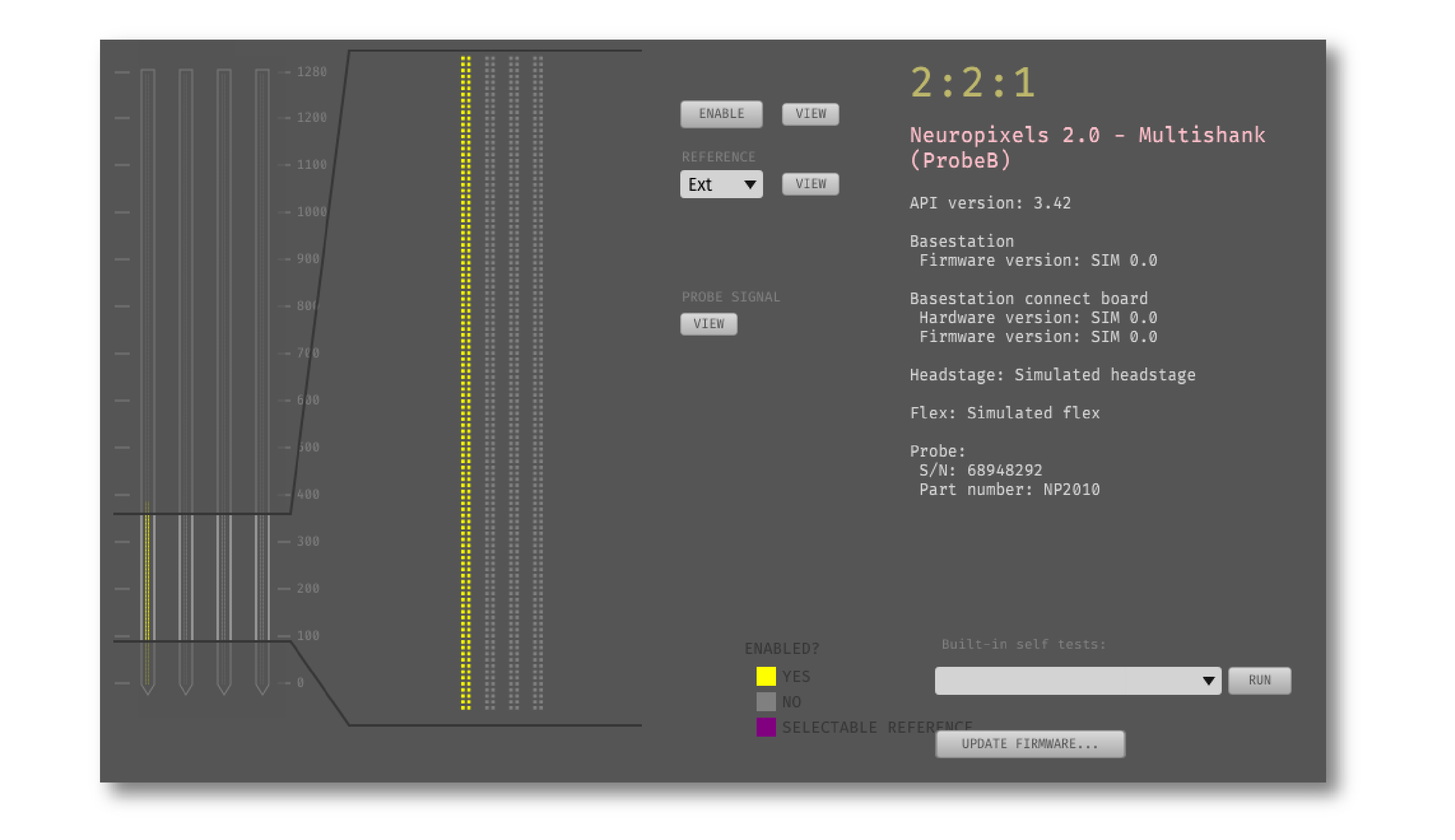
And for a Neuropixels 2.0 (quad base) probe:
Electrode selection#
The interface on the left allows you to select/deselect electrodes from different banks. Use the mini probe overview visualization to scroll to the electrodes you want to activate, click or drag to select them in the zoomed visualization, and then click the “ENABLE” button. Selecting electrodes on one bank will automatically deactivate the electrodes on all other banks that are connected to the same set of channels.
You can also select pre-defined electrode configurations from the “Electrode Preset” drop-down menu. This is a much faster way to switch between commonly used electrode layouts.
Gain and filter settings#
For 1.0, NHP, and Ultra probes, you can change the following settings:
AP Gain (amplifier gain for AP channels, 50x-3000x; default = 500x)
LFP Gain (amplifier gain for LFP channels, 50x-3000x; default = 250x)
AP Filter Cut (ON = 300 Hz high-pass filter active, OFF = filter inactive; default = ON)
Reference selection#
All probe types include a Reference drop-down menu that can be used to select one of the following reference types:
External (default) - references signals to the dedicated reference pad on the probe/flex cable. This pad can be connected to a wire immersed in saline above the brain (for acute recordings) or a screw embedded in the skull (for chronic recordings). It’s common to use a wire to bridge the reference pad to the ground pad, to avoid the need for a separate reference wire.
Tip - references signals to the large pad at the tip of the probe (or the tip of a particular shank, in the case of the 4-shank Neuropixels 2.0). The tip reference will likely reduce your overall noise levels, but it will also lead to leakage of low-frequency signals across all channels. If you want to do any analysis of the local field potential, you need to be sure to keep at least a few channels outside the brain, in order to subtract their signals offline.
Neuropixels 2.0 probes have an additional reference option:
Ground - same as External, but with the ground and reference connected internally, so no wire bridge is needed.
Note
As of GUI version 0.6.0, it’s no longer possible to select the “Internal” reference channels of a Neuropixels probe. These channels are not suitable to use as a reference due to their high impedance.
Caution
When using multiple PXI basestations in the same chassis, some users have reported problems with the External reference. This manifests as randomly occurring saturating events on the LFP channels, combined with a sudden drop in gain on the AP channels. Such events are not seen when using the Tip reference.
Activity view#
Pressing the “VIEW” button in the “Probe Signal” area will toggle a live display of the amplitude range of each channel whenever acquisition is active. For Neuropixels 1.0 probes, activity can be viewed for the AP band or LFP band.
Added in version 2.0.0: The activity view includes two toggle buttons that control how the incoming data is processed prior to visualization.
BP FILTER - When enabled, applies a 300-6000 Hz bandpass filter to the data before calculating peak-to-peak amplitudes for visualization
CAR - When enabled, applies common average referencing to the data before calculating peak-to-peak amplitudes for visualization
Note
These filtering and referencing options only affect the activity visualization and do not modify the outgoing data sent to downstream plugins or saved to disk.
Saving, loading, and copying settings#
Default loading and saving#
Any changes made to the probe settings will be automatically re-applied when you re-start the GUI, provided you have checked Reload on startup from the “File” menu. Settings will first be transferred by probe serial number. If no matching serial number is found, settings will be inherited from a probe of the same type. Settings cannot be transferred between probes of different types (e.g. Neuropixels 1.0 to Neuropixels 2.0).
Copying settings between probes#
Settings can be transferred between probes using the “COPY”, “PASTE”, and “APPLY TO ALL” buttons:
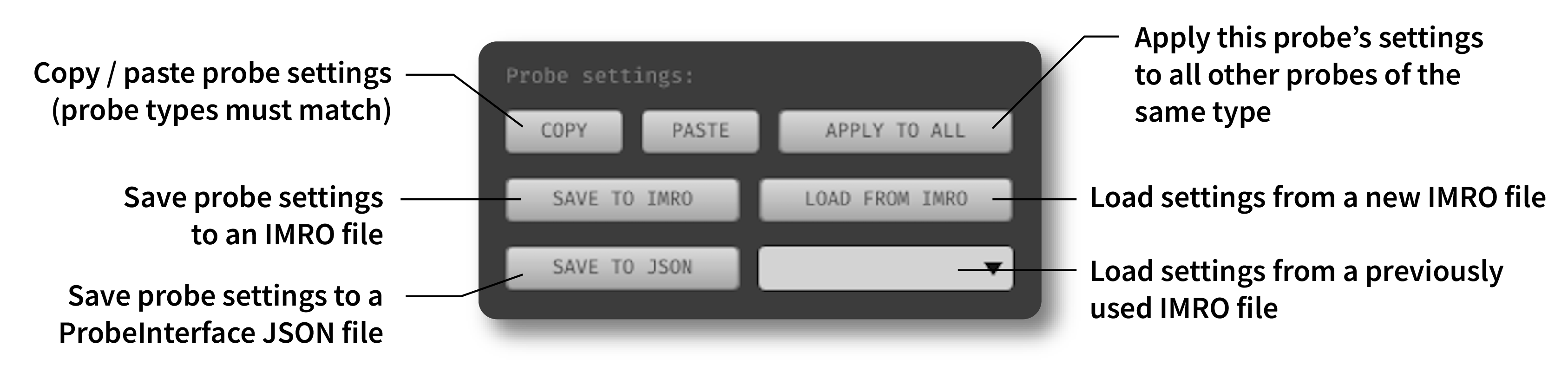
Settings can only be applied to probes of matching types (e.g. 1.0, NHP, Ultra, 2.0).
IMRO files#
Settings for individual probes can also be loaded using SpikeGLX “IMec Read Out” (IMRO) tables, using the “LOAD FROM IMRO” button.
The IMRO format is specified here. If you’ve saved a probe configuration using SpikeGLX or some other software, you can apply that configuration to a probe in the Open Ephys GUI by reading in an IMRO file. The only caveat is that Open Ephys does not allow individual channels to have different gain or reference settings, so those will be inherited from the last channel in the file.
You can save the configuration for a particular probe into IMRO format using the “SAVE TO IMRO” button. These files can be used in SpikeGLX or any other software that can read the IMRO format.
Any IMRO files that have been loaded previously will appear in the drop-down menu below the “LOAD FROM IMRO” button, so they can be accessed more easily.
Important
IMRO files are not checked to ensure that all specified electrodes can actually be selected simultaneously. If you have generated an IMRO file with custom software (i.e., not through Open Ephys or SpikeGLX), be sure to verify that selected electrodes are not connected to overlapping channels before attempting to load it.
ProbeInterface JSON files#
If you’re performing offline analysis with SpikeInterface, it may be helpful to have information about your probe’s channel configuration stored in a JSON file that conforms to the ProbeInterface specification. To export a ProbeInterface JSON file, simply press the “SAVE TO JSON” button.
Rescanning basestations#
Pressing the “rescan” button in the upper right corner of the plugin editor will initiate a basestation rescan. If probes have been added, moved, or removed, they will be detected automatically. Prior settings will be transferred based on probe serial number.
Caution
After plugging or unplugging probes, do not try to start acquisition without triggering a re-scan or re-launching the GUI.
Plugin data streams#
The Neuropixels PXI plugin sends data from all connected probes through the GUI’s signal chain unless they have been disabled. To disable data transmission, you can press the “ENABLE” button underneath the probe name. The probe’s icon will turn red, and its data will not be available to downstream plugins.
Neuropixels 1.0, NHP, or Ultra probes have two data streams:
384 channels of AP band data, sampled at 30 kHz (e.g. “ProbeA-AP”)
384 channels of LFP band data, sampled at 2.5 kHz (e.g. “ProbeA-LFP”)
Neuropixels 2.0 single-shank and quad-shank probes have only one data stream:
384 channels of wide-band data, sampled at 30 kHz.
Neuropixels 2.0 quad base probes have four data streams (one for each shank):
384 x 4 channels of wide-band data, sampled at 30 kHz.
Note
In all downstream plugins, each stream retains its own set of parameters. For example, in the Bandpass Filter, there are independent high cut and low cut settings for each stream. It’s important to be aware that settings for one stream are not automatically applied to other streams. If you are recording from many probes simultaneously, be sure to use the Stream Selector interface in downstream plugins to confirm that the appropriate settings have taken effect for all incoming data streams.
Customizing stream names#
Clicking on the slot number for a given basestation will open up an interface for customizing the names of the data streams generated by the Neuropixels PXI plugin. By default, each probe is assigned a name based on the order that it’s detected: ProbeA, ProbeB, ProbeC, etc. While this is fine for most use cases, there are some situations where other behavior is desirable. Therefore, the plugin includes four different schemes for naming data streams, which can be applied independently for each basestation:
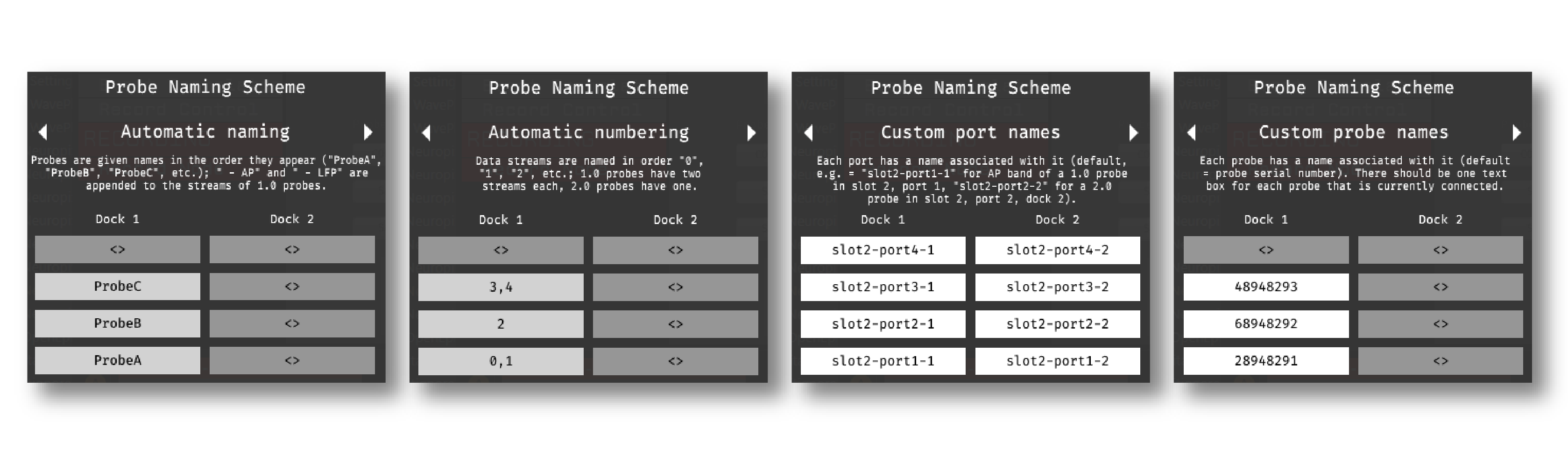
Automatic naming: Probes names are assigned automatically, based on the order in which they are detected. Any 1.0 probes will have “-AP” and “-LFP” appended to their respective streams. The naming interface displays the names that will be applied when using this scheme, but they cannot be edited.
Automatic numbering: Numeric stream names are assigned automatically, based on the order in which they are detected. This scheme will produce file names that look like those from GUI version 0.5.X and earlier, which did not have the ability to apply custom names to individual streams. The naming interface displays the names that will be applied when using this scheme, but they cannot be edited.
Custom port names: Probe names are assigned by port/dock. This is useful if you have probes placed in a particular physical configuration, and always want a probe in a certain position to have the same name, regardless of which other probes are connected.
Custom probe names: Probe names are assigned by serial number. This is useful if you have probes chronically implanted and would like to associate the subject ID with a particular probe.
Caution
All stream names must be unique for a given plugin. Currently, it’s possible to inadvertently assign the same name to multiple probes, either by using the same port-specific or probe-specific names across basestations. Name conflicts must be checked manually in order to prevent crashes when starting recording.
Synchronization settings#
Properly configuring your synchronization signals is critical for Neuropixels recordings. Each probe will have a slightly different sample rate between 29999.9 and 30000.1 Hz, so you cannot simply count samples to figure out how much time has elapsed for a given data stream. Therefore, every data source (including individual basestations, NI hardware, etc.) must share a hardware sync line in order for samples to be accurately aligned offline.
Each Neuropixels basestation contains one SMA connector for sync input. The behavior of these connectors is configured using the synchronization interface within the plugin editor:
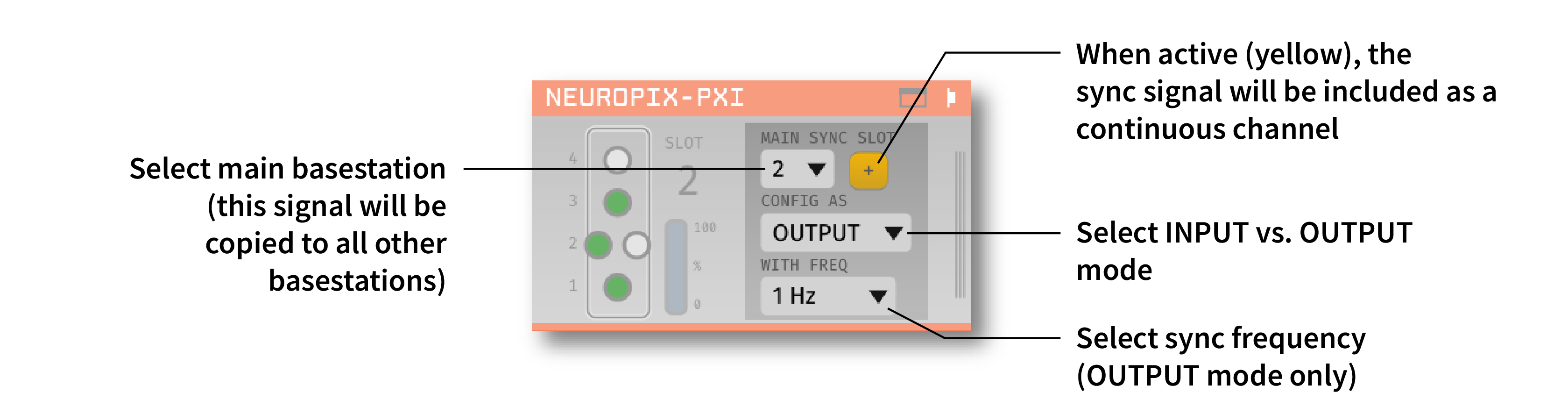
The top drop-down menu allows you to select one basestation’s SMA connector to serve as the “main” sync. The signal on this line will be automatically copied to the sync inputs of all other basestations.
The “+” button allows you to toggle whether or not the sync line is appended to all data streams as a continuous channel. When this button is orange, each stream will include a 385th channel containing the state of the sync line. This will make the Binary Format data files saved by the Record Node compatible with a variety of SpikeGLX-associated offline processing tools, such as CatGT. This button should be enabled only if you plan to use these tools. Regardless of whether or not this option is enabled, the sync rising and falling edges will be transmitted as events to downstream processors.
The second drop-down menu allows you to configure the main sync SMA as INPUT or OUTPUT. In INPUT mode, an external digital input must be connected to the SMA. In OUTPUT mode, the main basestation will generate its own sync signal at 1 Hz.
Probe Survey Mode#
Added in version 2.0.0: The Neuropixels PXI plugin includes a Survey interface that allows you to quickly assess neural activity across one or more probes. This is particularly useful for identifying active brain regions and selecting optimal electrode sites before starting your main recording session.
Accessing the Survey interface#
To open the Survey interface, click on the “Survey” tab in the plugin’s canvas window (opened by clicking the “tab” or “window” button in the plugin editor).

The Survey interface consists of two main areas:
Survey Settings panel (left side) - Configure survey parameters and select which probes/banks/shanks to survey
Probe Activity View (right side) - Visualize electrode activity as a heatmap for all connected probes
Survey Settings#
The settings panel provides the following controls:
- Time per bank/shank
Set the duration (in seconds) to acquire data from each bank/shank combination. Options range from 2 seconds to 10 minutes. Longer durations will yield more accurate activity measurements, but will also increase the total survey time.
- Record survey to disk
When checked, all data acquired during the survey will be saved to disk. This requires at least one Record Node to be present in the signal chain. If unchecked, the average peak-to-peak amplitudes for each electrode will be displayed, and can optionally be exported as a JSON file.
- Activity view options
BP FILTER - Toggles a 300-6000 Hz bandpass filter on the data used to calculate peak-to-peak amplitudes
CAR - Toggles common average referencing for the peak-to-peak value calculations
- Probe configuration table
This table displays all connected probes and allows you to:
Use - Check/uncheck to include/exclude probes from the survey
Probe - Probe name and identifier
Type - Probe type (e.g., “1.0”, “2.0 Multi Shank”, “2.0 Quad Base”)
Banks - Click to select specific banks to survey (default: “All”)
Shanks - Click to select specific shanks for multi-shank probes (default: “All”)
- Save results
Exports the peak-to-peak activity values of all selected probes from the most recent survey to a JSON file for further analysis.
- Amplitude scale
Adjusts the color scale range for the probe activity heatmap display.
Running a survey#
To start a survey:
Configure which probes, banks, and shanks you want to survey using the probe configuration table
Set the desired time per bank/shank
(Optional) Enable recording to disk if you want to save the survey data
Click the RUN SURVEY button

The survey will automatically:
Cycle through each selected shank/bank combination
Acquire data for the specified duration
Calculate the average peak-to-peak amplitude for each channel
Display a progress bar showing the current status
You can cancel the survey at any time by clicking the “Cancel” button in the progress dialog.
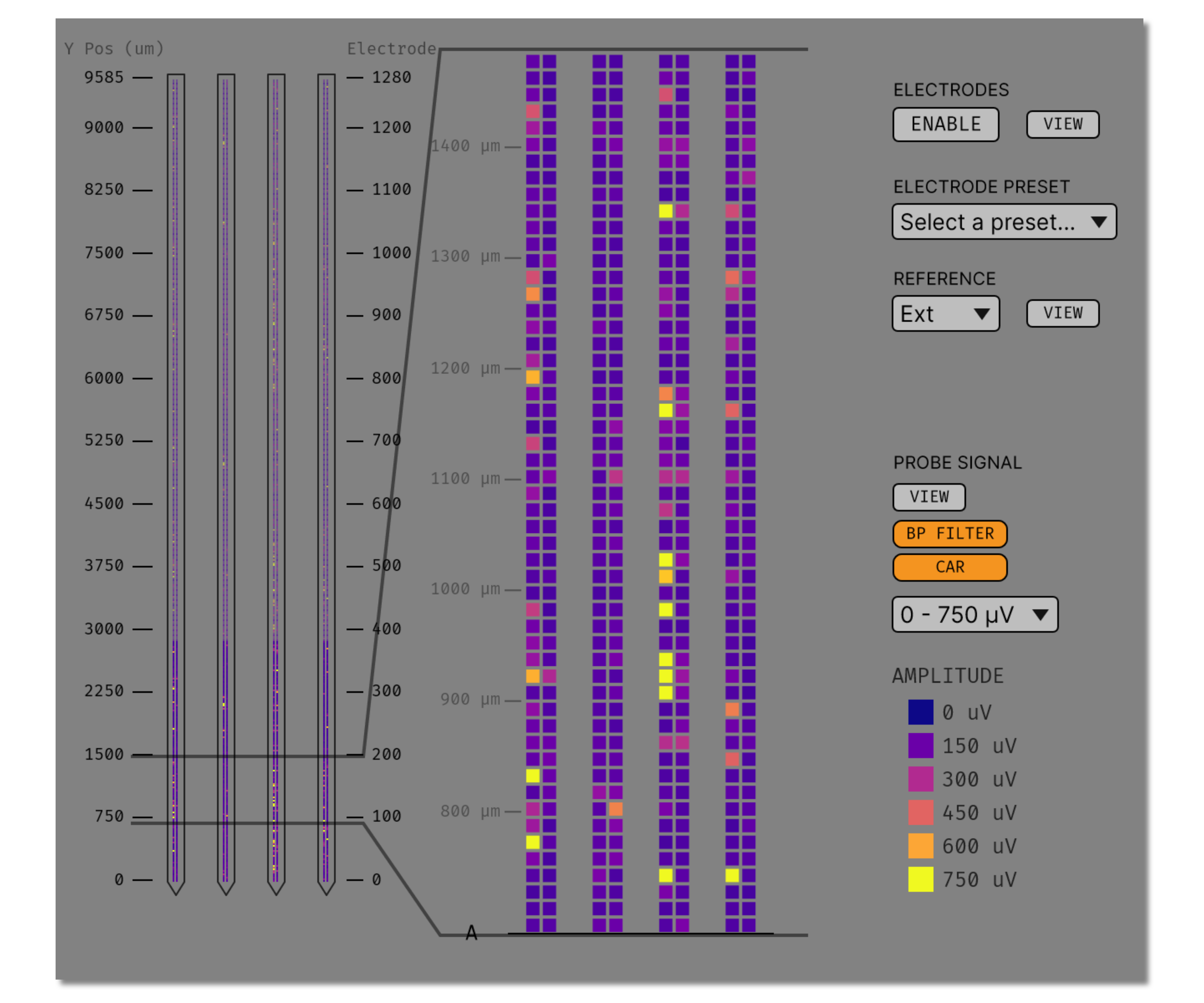
Viewing survey results#
Once the survey is complete, the Probe Activity View displays a heatmap showing the peak-to-peak activity for each electrode across all surveyed banks and shanks. Warmer colors (yellow/orange) indicate higher activity levels, while cooler colors (purple/blue) indicate lower activity.

The heatmap makes it easy to:
Identify which regions of the probe are most active
Compare activity levels across different banks or shanks
Make informed decisions about electrode site selection
You can also view the survey results in individual probe settings interfaces by enabling the “Probe Signal” view, which overlays the activity information on the electrode selection interface.
Simulation mode#
When running the plugin in simulation mode, you’ll have the option of selecting up to four different probes to acquire data from. This is useful for familiarizing yourself with the settings interfaces for different probe types, or testing your signal chain in the absence of any Neuropixels hardware.
The simulated AP band data was designed to make the probe activity view look interesting; the simulated LFP band data is sine waves with amplitudes that vary across channels.
Built-in self tests#
If you have a probe that’s not working properly, these tests can be used to help pinpoint where the problem lies. It’s not recommended to run the tests prior to every recording; the tests are only necessary to diagnose an issue with a probe that is not transmitting data.
To run each test, select one from the drop-down menu, and click the “RUN” button. After the test completes, the name of the test will be updated to indicated whether it passed or failed.
Name |
Duration |
Purpose |
|---|---|---|
Test probe signal (removed in plugin v2.0.0) |
30 s |
Analyzes if the probe performance falls within a specified tolerance range, based on a signal generated by the headstage. Probes that are fully functional can still fail this test, so it’s not a definitive indicator of probe health. |
Test probe noise (removed in plugin v2.0.0) |
30 s |
Calculates probe noise levels when electrode inputs are shorted to ground. Similar to the probe signal test, this test is not a definitive indicator of probe health, so failures can be safely ignored. |
Test PSB bus |
<1 s |
Verifies whether signals are transmitted accurately to the headstage via the parallel serial bus. If this test fails, it usually indicates that the probe is not properly seated in the headstage. |
Test shift registers |
1 s |
Verifies the functionality of the shank and base shift registers. If this test fails, it means the probe electronics have become critically damaged. Even if data is being transmitted, there’s a possibility that it may be corrupted. |
Test EEPROM |
1 s |
Tests the EEPROM memory storage on the flex, headstage, and BSC. |
Test I2C |
<1 s |
Verifies the functionality of the probe’s I2C interface. This interface must be intact for proper functioning of the probe. |
Test Serdes |
<1 s |
Tests the integrity of the serial communication over the probe cable. |
Test Heartbeat |
3 s |
Checks for a 1 Hz heartbeat signal between the headstage and BSC. This test indicates whether basic communication between the headstage and basestation is working. |
Test Basestation |
<1 s |
Tests the connectivity between the computer and the basestation FPGA board via the PXIe interface. |
Note
If the “probe signal” and “probe noise” tests fail, it does not necessarily indicate that the probe is broken. If your probe is successfully transmitting data, the outcome of all of these tests (except the shift register test) can be safely ignored.
Headstage tests#
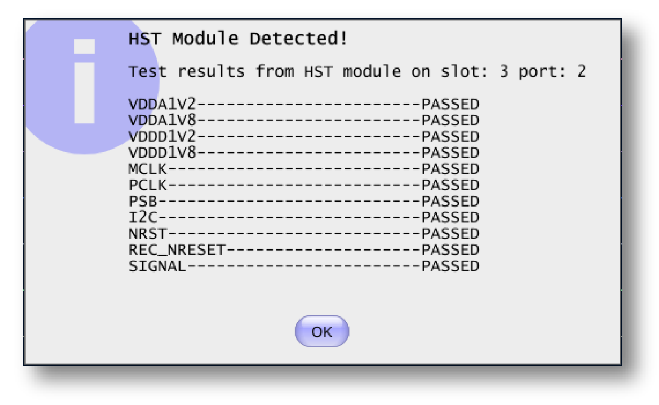
If you have a headstage test module, you can run a suite of tests to ensure the headstage is functioning properly. When the Neuropix plugin is dropped into the signal chain and at least one headstage test module is connected to the PXI system, the GUI will automatically run all headstage tests and output the results in a popup window:
Note
The headstage tests have been re-enabled as of plugin version 0.5.x. However, we have also found that the headstage tests are rarely needed to accurately diagnose a problem with data transmission. If you are unsure whether your headstage is functional, swapping it out with a different headstage is usually more informative than running the headstage tests.
Updating basestation firmware#
Version 2.0.x of the Neuropixels PXI plugin will require a basestation firmware update. The latest firmware (BS226, BSC233) can be downloaded here.
The currently installed firmware version will appear in the info section of the Neuropixels settings interface (upper right text block). If your basestation firmware version is “3.0226” and your basestation connect board firmware version is “4.0233”, you already have the latest firmware installed.
If you need to update your firmware, first click the “UPDATE FIRMWARE” button to open the firmware update interface:

Next, select the .bin file for the basestation connect board (QBSC*.bin), and click “UPLOAD”.
Immediately after the basestation connect board firmware upload finished, use the lower drop-down menu to select a .bin file for the basestation (BS*.bin), and click “UPLOAD”.
Finally, once the basestation firmware is finished uploading, restart your computer and power cycle the PXI chassis for the changes to take effect.
Note
If you need to update the firmware for multiple basestations in one chassis, please perform all firmware updates prior to restarting your chassis/computer. Alternatively, you can update each basestation separately if only one basestation at a time is inserted into the chassis. The Neuropixels plugin can only communicate with sets of basestations that are running the same firmware.
Remote control#
A number of Neuropixels probe settings can be changed via the GUI’s built-in HTTP server. Commands are sent as “config messages” to the Neuropix-PXI processor.
The following commands are available:
NP INFO: returns a JSON string containing information about all available probesNP REFERENCE <bs> <port> <dock> <EXT/TIP>: set the reference for a specific probeNP GAIN <bs> <port> <dock> <AP/LFP> <gainval>: set the AP or LFP gain for a specific probe (Neuropixels 1.0 only)NP FILTER <bs> <port> <dock> <ON/OFF>: turn the AP filter cut on or off (Neuropixels 1.0 only)NP SELECT <bs> <port> <dock> <electrode> <electrode> <electrode> ...: select electrodes by index
Note that the bs, port, and dock parameters all use 1-based indexing, and the dock parameter is always 1 for Neuropixels 1.0 probes.
For example, the NP SELECT command can be used to automatically cycle through different electrode banks. The following code shows how to do this using the open-ephys-python-tools package (version 0.1.6 and higher):
import numpy as np
import time

from open_ephys.control import OpenEphysHTTPServer

gui = OpenEphysHTTPServer()

# configuration parameters
processor_id = 106
basestation = 4
port = 3
dock = 1 # always 1 for NP 1.0

command = f'NP SELECT {basestation} {port} {dock} '

electrodes = np.arange(1,385) # 1-based indexing
electrode_string = ' '.join(electrodes.astype('str'))

gui.config(processor_id, command + electrode_string)

gui.record(60) # record for 60 seconds

electrodes = np.arange(384,767) # 1-based indexing
electrode_string = ' '.join(electrodes.astype('str'))

gui.config(processor_id, command + electrode_string)

gui.record(60) # record for 60 seconds