RHD Rec Controller#
Plugin Type |
Source |
Platforms |
Windows, Linux, macOS |
Built in? |
No; install via RHD Recording Controller |
Key Developers |
Josh Siegle, Aarón Cuevas López |
Source Code |
Installing and upgrading#
The RHD Rec Controller plugin is not included by default in the Open Ephys GUI. To install, use ctrl-P or ⌘P to open the Plugin Installer, browse to the “RHD Recording Controller” plugin, and click the “Install” button. After installation, RHD Rec Controller will appear in the processor list on the left side of the GUI’s main window.
The Plugin Installer also allows you to upgrade to the latest version of this plugin, if it’s already installed. The plugin must be removed from the signal chain prior to upgrading.
Plugin configuration#
Headstages#
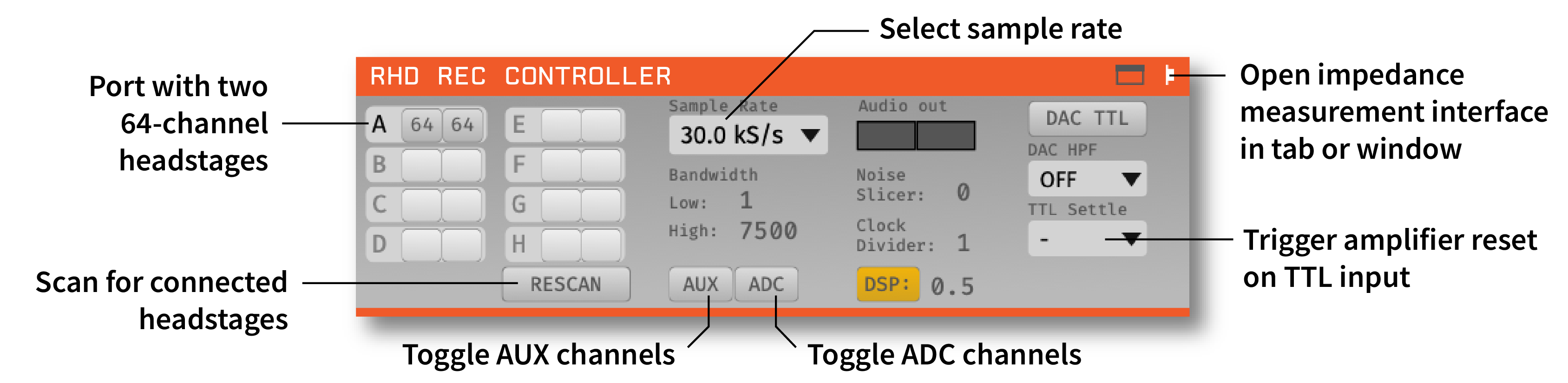
On the left-hand side of the module, there are slots for each of 16 possible headstages (A1, A2, B1, B2, etc.). Each row corresponds to one 12-channel Omnetics connector on the input board (A-D on the 512 channel board, and A-H on the 1024 channel board), and each column corresponds to one headstage on that input. Up to two headstages can be connected to each input using a dual headstage adapter. The module will automatically detect headstages that are connected, as well as whether they contain a 64- or 32-channel Intan chip. However, if you add or remove headstages after the module has been loaded, you need to press the “RESCAN” button.
Using 16-channel headstages#
Clicking on the button for one of the detected headstages will toggle it between 32-channel and 16-channel mode. This is necessary because the difference between 16-channel and 32-channel headstages cannot detected in software, and has to be selected manually.
Sample rate selection#
Sample rates between 1 and 30 kHz can be selected with this drop-down menu. This will determine the sample rate for all headstages, digital inputs, and ADCs.
Bandwidth interface#
Used to determine the settings for the analog high and low cut filters on the Intan chip. Because only certain values are possible for each, the number that appears may be different from the number you typed in; the chip will automatically select the nearest value, and that will be indicated in the GUI.
Turning on AUX channels#
Pressing the “AUX” button toggles the headstage AUX inputs on and off. Each Intan chip can communicate with up to 3 “auxiliary” inputs, which are connected to a 3-axis accelerometer on some headstages. If the button is off (gray), the AUX channels on each headstage will be ignored. If the button is on (yellow), they will be sent as parallel data channels, with the same sampling rate as the neural data.
Turning on ADC channels#
Pressing the “ADC” button toggles the ADC inputs on and off. If the button is off (gray), the ADC channels acquired by the board will be discarded. If the button is on (yellow), they will be sent as parallel data channels, with the same sampling rate as the neural data. To use these channels, an I/O board needs to be connected to the second HDMI port from the left.
Audio output#
The “AUDIO OUT” interface will allow you select up to 2 channels to preview in real time, directly from the acquisition board. There is an audio jack on the board that’s mirrored to the first two analog output channels (CH1 and CH2 of the Digital & Analog I/O for L and R sound outputs when connected to HDMI port for analog output). To select a channel for monitoring, click on one of the two “Audio Out” buttons to reveal the pop-up channel selector.
Note
In general, we recommend using the Audio Monitor plugin to listen to spikes through your computer’s speakers, as it is much more flexible.
Noise slicer#
Sets the threshold for the noise slicer on the hardware audio outputs (sets any values below threshold to zero, to improve the signal-to-noise ratio). In practice, this doesn’t work particularly well.
Clock divider#
NOT USED IN THIS PLUGIN
DAC TTLs#
When this button is on, the digital-to-analog converter (DAC) will generate TTL outputs whenever the output signal crosses a threshold. Note that this is an untested feature and not recommended for experiments.
DAC High-pass filter#
Sets the high-pass filter cutoff frequency for the DAC outputs.
TTL settle#
Ties one of the digital inputs on the acquisition board/evaluation board to the “fast-settle” functionality of the Intan chips. If the selected digital input channel goes high, it will trigger the reset of the amplifiers across all headstages.
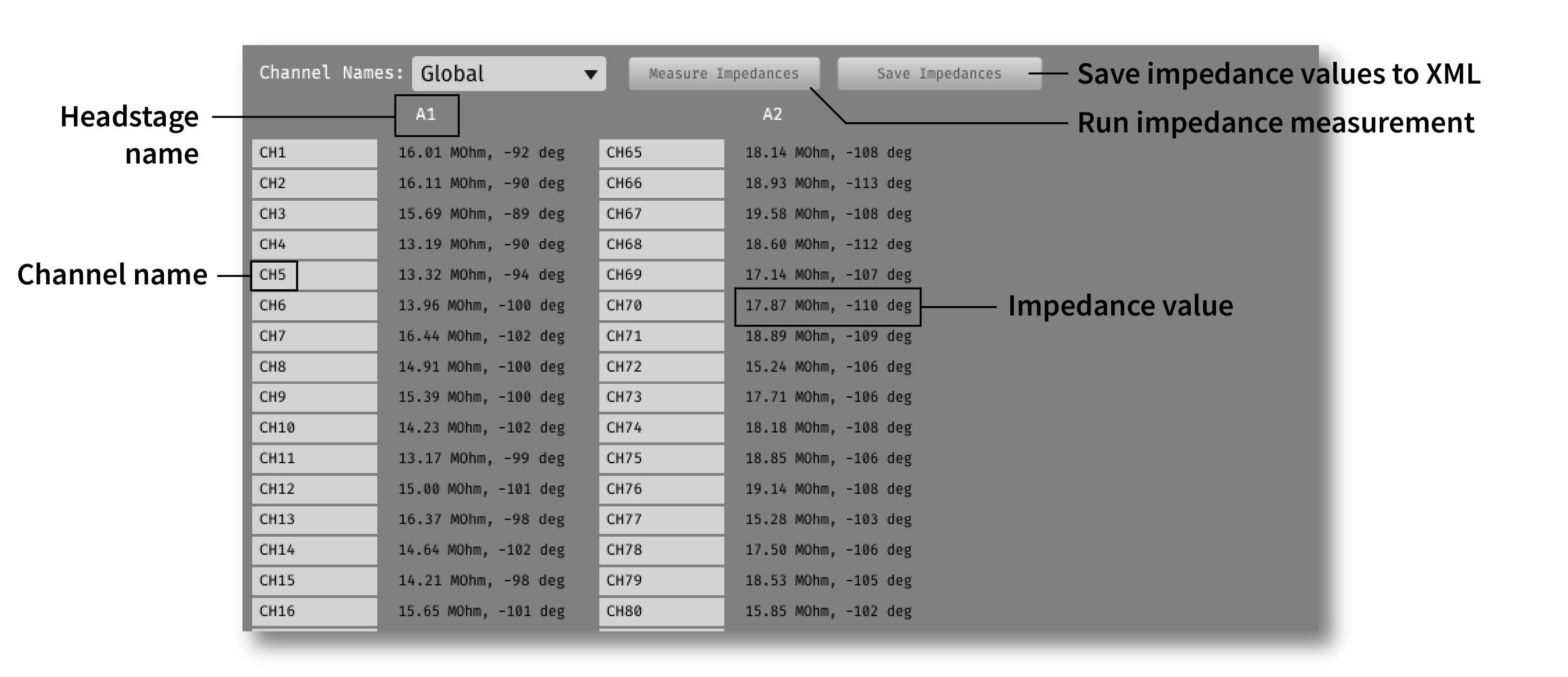
Impedance testing#
To open the impedance measurement interface, click the “window” or “tab” buttons at the top of the plugin editor. This will bring up an impedance measurement interface that looks like this:
Closed-loop feedback#
Installing the “RHD Recording Controller” plugins will also install the “Rec Controller Output” plugin, which can be used to trigger the digital outputs of the acquisition board.
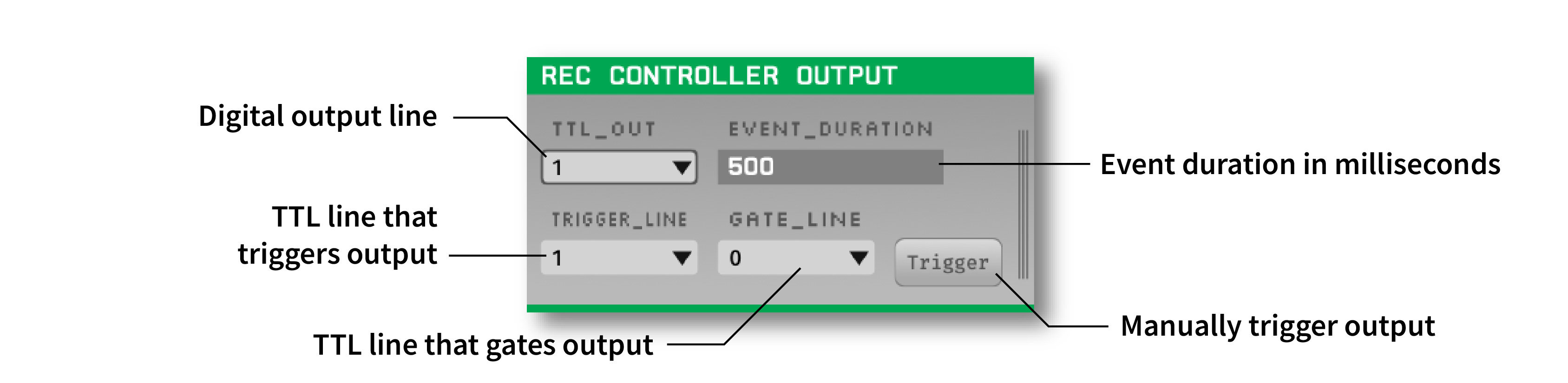
If this plugin is placed downstream of the RHD Rec Controller plugin, as well as a plugin that generates TTL events (e.g., Crossing Detector or Ripple Detector), the digital output channel specified by the TTL_OUT parameter will be temporarily set to high each time a TTL event is received on the TRIGGER_LINE. The approximate duration of this event (in milliseconds) is set by the EVENT_DURATION parameter.
This configuration can be used to perform closed-loop feedback experiments in which some feature of the neural data (such as phase of an oscillation, or the presence of a ripple event), is used to trigger stimulation.