XDAQ#
Plugin Type |
Source |
Platforms |
Windows, Linux, macOS |
Built in? |
No |
Key Developers |
Stone Lin |
Source Code |
Tip
For more in-depth documentation on the XDAQ, please refer to the XDAQ help site.
Plugin configuration#
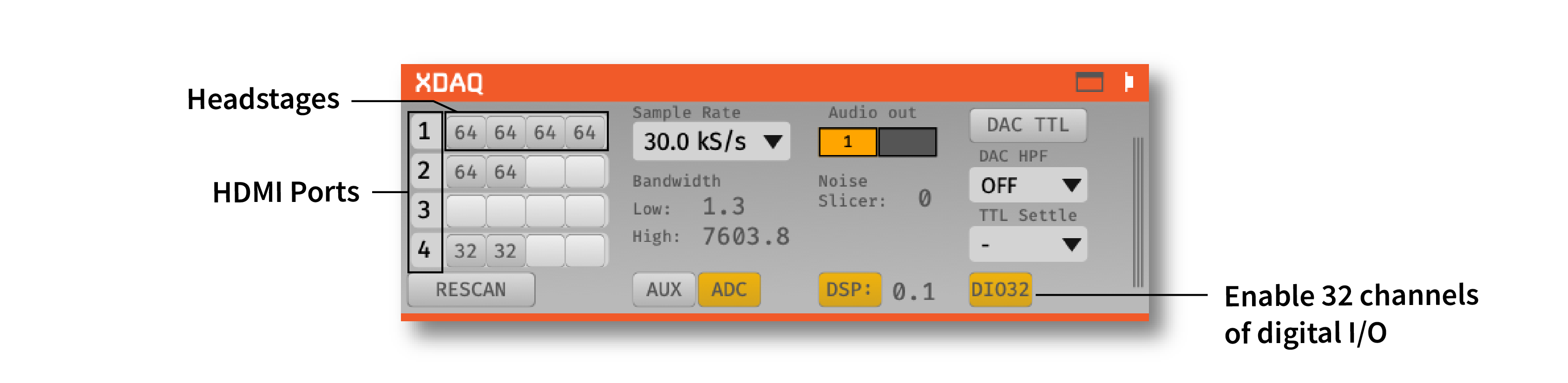
Headstages#
XDAQ Systems (ONE, CORE…) can support up to 16 RHD headstage chips depending on model and configuration. Each row corresponds to one HDMI port on the XDAQ, and each column corresponds to one headstage chip on that port:

X-Headstages are manufactured using advanced packaging technology. Thus, one X-Headstage may contain multiple headstage chips and will display multiple chips in the GUI. For example, an X6R128 headstage will display as two 64-channel headstages in the GUI.
Each XDAQ ONE port supports up to 4 RHD chips (2 for XDAQ CORE). Use an adapter to run multiple X-Headstages if necessary.
The module will automatically detect headstages that are connected. However, if you add or remove headstages after the module has been loaded, you need to press the “RESCAN” button.
Sample rate selection#
Sample rates between 1 and 30 kHz can be selected with this drop-down menu. This will determine the sample rate for all headstages, digital inputs, and ADCs.
Bandwidth interface#
Used to determine the settings for the analog high and low cut filters on the Intan chip. Because only certain values are possible for each, the number that appears may be different from the number you typed in; the chip will automatically select the nearest value, and that will be indicated in the GUI.
Audio output#
The “AUDIO OUT” interface will allow you select up to 2 channels to preview in real time, directly from the acquisition board/evaluation board. There is an audio jack that’s mirrored to the first two analog output channels (CH1 and CH2 of the Analog I/O for L and R sound outputs when connected to HDMI port for analog output). To select a channel for monitoring, click on one of the two “Audio Out” buttons to reveal the pop-up channel selector.
Noise slicer#
Sets the threshold for the noise slicer on the hardware audio outputs (sets any values below threshold to zero, to improve the signal-to-noise ratio). In practice, this doesn’t work particularly well.
ADC selection#
Pressing the “ADC 1–8” button toggles the ADC inputs on and off. If the button is off (gray), the ADC channels on the acquisition board/evaluation board will be discarded. If the button is on (yellow), they will be sent as parallel data channels, with the same sampling rate as the neural data. A Digital & Analog I/O board needs to be connected to the second HDMI port from the left.
DAC TTLs#
UNTESTED FEATURE
DAC High-pass filter#
UNTESTED FEATURE Sets the high-pass filter cutoff for the DAC outputs
TTL settle#
UNTESTED FEATURE Ties one of the digital inputs on the acquisition board/evaluation board to the “fast-settle” functionality of the Intan chips. If the selected digital input channel goes high, it will trigger the reset of the amplifiers across all headstages.
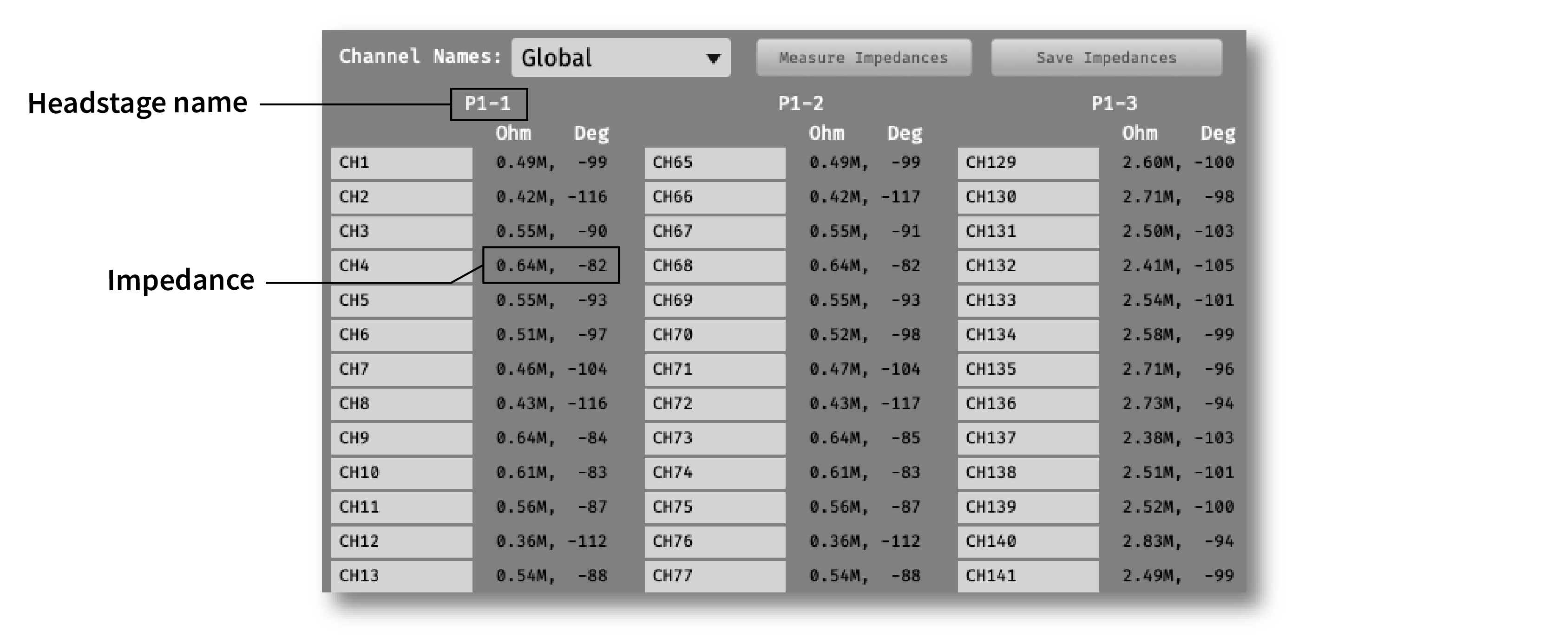
Impedance testing#
To open the impedance measurement interface, click the “window” or “tab” buttons at the top of the plugin editor. This will bring up an impedance measurement interface that looks like this: